ATM as a High-Speed, Connection-Oriented Transmission Technology

This article discusses the concept of Asynchronous Transfer Mode (ATM) and its applications in broadband networks. It highlights the key features of ATM, such as its high speed, low delay, and fixed-size packet transmission, and explores its implementation in both ISDN and non-ISDN environments. The article also covers the driving issues for LAN changes, including traffic integration and LAN interoperability with mobile and wireless nodes.
- Uploaded on | 1 Views
-
 danna
danna
About ATM as a High-Speed, Connection-Oriented Transmission Technology
PowerPoint presentation about 'ATM as a High-Speed, Connection-Oriented Transmission Technology'. This presentation describes the topic on This article discusses the concept of Asynchronous Transfer Mode (ATM) and its applications in broadband networks. It highlights the key features of ATM, such as its high speed, low delay, and fixed-size packet transmission, and explores its implementation in both ISDN and non-ISDN environments. The article also covers the driving issues for LAN changes, including traffic integration and LAN interoperability with mobile and wireless nodes.. The key topics included in this slideshow are ATM, Asynchronous Transfer Mode, high speed, low delay, fixed size packets, Broadband ISDN, LAN changes, traffic integration, multimedia, quality of service, LAN interoperability, mobile and wireless nodes,. Download this presentation absolutely free.
Presentation Transcript
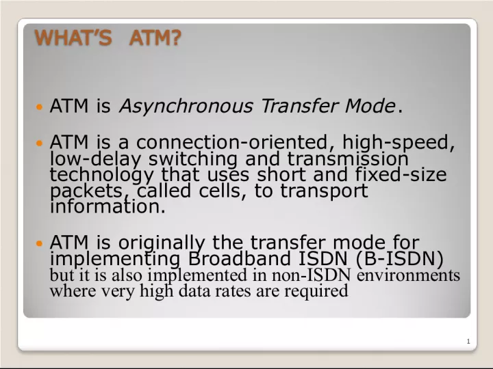
1. WHATS ATM? WHATS ATM? ATM is Asynchronous Transfer Mode . ATM is a connection-oriented, high-speed, low-delay switching and transmission technology that uses short and fixed-size packets, called cells, to transport information. ATM is originally the transfer mode for implementing Broadband ISDN (B-ISDN) but it is also implemented in non-ISDN environments where very high data rates are required 1
2. Networks: ATM 2 Issues Driving LAN Changes Issues Driving LAN Changes Traffic Integration Voice, video and data traffic Multimedia became the buzz word One-way batch Web traffic Two-way batch voice messages One-way interactive Mbone broadcasts Two-way interactive video conferencing Quality of Service guarantees (e.g. limited jitter, non-blocking streams) LAN Interoperability Mobile and Wireless nodes
3. Networks: ATM 3 MUX ` Wasted bandwidth ATM TDM 4 3 2 1 4 3 2 1 4 3 2 1 4 3 1 3 2 2 1 Voice Data packet s Image s Figure 7.37 Asynchronous Transfer Mode (ATM) Asynchronous Transfer Mode (ATM)
4. Networks: ATM 4 ATM ATM ATM standard (defined by CCITT) is widely accepted by common carriers as mode of operation for communication particularly BISDN. ATM is a form of cell switching using small fixed-sized packets. Header Payload 5 Bytes 48 Bytes Figure 9.1 Basic ATM Cell Format
5. Networks: ATM 5 ATM Conceptual Model Four Assumptions ATM Conceptual Model Four Assumptions 1. ATM network will be organized as a hierarchy . Users equipment connects to networks via a UNI (User-Network Interface). Connections between provided networks are made through NNI (Network-Network Interface). 2. ATM will be connection-oriented . A connection (an ATM channel) must be established before any cells are sent.
6. BROADBAND AND B-ISDN BROADBAND AND B-ISDN Broadband: "A service or system requiring transmission channel capable of supporting rates greater than the primary rate. Broadband-Integrated Service Digital Network (B- ISDN): A standard for transmitting voice, video and data at the same time over fiber optic telephone lines The goal of B - ISDN is to accommodate all existing services along with those that will come in the future. The services that BISDN will support include (1) narrowband services, such as voice, voiceband data, facsimile, telemetry, videotex, electronic mail, (2) wideband services such as T1, and (3) broadband services such as video conference, high speed data, video on demand. BISDN is also to support point- to - point, point-to-multipoint and multipoint-to-multipoint connectivities. 6
7. ATM OVERVIEW ATM OVERVIEW Used in both WAN and LAN settings Signaling (connection setup) Protocol: Packets are called cells (53 bytes) 5-byte header + 48-byte payload Commonly transmitted over SONET other physical layers possible Connections can be switched (SVC), or permanent (PVC). ATM operates on a best effort basis. 7
8. ATM guarantees that cells will not be disordered. Two types of connections: Point-to-point Multipoint (Multicast) Four Types of Services: CBR (Constant Bit Rate) VBR (Variable Bit Rate) ABR (Available Bit Rate) Flow Control, Rate- based, Credit- based UBR (Unspecific Bit Rate) No Flow control. 8
9. ATM Characteristics ATM Characteristics No error protection or flow control on a link-by-link basis. ATM operates in a connection-oriented mode. The header functionality is reduced. The information field length is relatively small and fixed. All data types are the same 9
10. Why ATM? Why ATM? International standard-based technology (for interoperability) Low network latency (for voice, video, and real- time applications) Low variance of delay (for voice and video transmission) Guaranteed quality of service High capacity switching (multi-giga bits per second) Bandwidth flexibility (dynamically assigned to users) 10
11. Why ATM? (cont) Why ATM? (cont) Scalability (capacity may be increased on demand) Medium not shared for ATM LAN (no degradation in performance as traffic load or number of users increases) Supports a wide range of user access speeds Appropriate (seamless integration) for LANs, MANs, and WANs Supports audio, video, imagery, and data traffic (for integrated services) 11
12. ATM NETWORKS ATM NETWORKS Public ATM Network: Provided by public telecommunications carriers (e.g., AT&T, MCI WorldCom, and Sprint) Interconnects private ATM networks Interconnects remote non-ATM LANs Interconnects individual users Private ATM Network: Owned by private organizations Interconnects low speed/shared medium LANs (e.g., Ethernet, Token Ring, FDDI) as a backbone network Interconnects individual users as the front-end LAN for high performance or multimedia applications 12
13. 13 Switches in the middle End systems of ATM
14. 14 Public ATM Network Token Ring Token Ring FDDI FDDI Mainframe Computer Video Video Video Ethernet Ethernet Mainframe Computer Edge Switch Ethernet File Server Private ATM Switch Edge Switch Edge Switch Edge Switch PBX PBX Voice Voice Private ATM Network FDDI
15. How ATM Works? How ATM Works? ATM is connection-oriented -- an end-to-end connection must be established and routing tables setup prior to cell transmission Once a connection is established, the ATM network will provide end-to-end Quality of Service (QoS) to the end users All traffic, whether voice, video, image, or data is divided into 53- byte cells and routed in sequence across the ATM network Routing information is carried in the header of each cell Routing decisions and switching are performed by hardware in ATM switches Cells are reassembled into voice, video, image, or data at the destination 15
16. 16 ATM Network H H H H H H H H Voice Video Data Voice Video Data BISDN Services BISDN Services Reassembly User Applications User Applications Workstation Workstation Multiplexing Demultiplexing H H H H H H Segmentation
17. 17 B-ISDN/ATM Protocol Reference Model B-ISDN/ATM Protocol Reference Model Source: Stallings: Data and Computer Communications Source: Stallings: Data and Computer Communications
18. ATM Protocol Reference Model ATM Protocol Reference Model 18 Convergence SAR ATM Access control Physical Layer CBR Signaling & control CLNS data CONS data Video Voice Plane management functions Higher layer protocols & functions Adaptation layer Transfer mode
19. Physical Medium Dependent sublayer Physical Medium Dependent sublayer Physical Medium Dependent Sublayer: depends on physical medium being used SONET/SDH: (Synchronous Optical Network / Synchronous Digital Hierarchy) transmission frame structure (like a container carrying bits); bit synchronization; bandwidth partitions (TDM); several speeds: OC3 = 155.52 Mbps; OC12 = 622.08 Mbps; OC48 = 2.45 Gbps, OC192 = 9.6 Gbps TI/T3 : transmission frame structure (old telephone hierarchy): 1.5 Mbps/ 45 Mbps unstructured : just cells (busy/idle) 19
20. ATM LAYER ATM LAYER The ATM layer provides for the transparent transport of fixed sized ATM layer service data units between communicating upper layer entities (e.g., ATM Adaptation Layer). A n interface between the AAL and the physical layer 20
21. ATM CELL ATM CELL 5-byte ATM cell header 48-byte payload Why?: small payload -> short cell-creation delay for digitized voice 21 Header Payload 5 Bytes 48 Bytes Leon-Garcia & Widjaja: Communication Networks
22. ATM CELL HEADER FORMAT (UNI) ATM CELL HEADER FORMAT (UNI) 22 GFC: Generic Flow Control VPI: Virtual Path Identifier VCI: Virtual Circuit Identifier PTI: Payload Type Indicator CLP: Cell Loss Priority HEC: Header Error Control UNI ( User-Network Interface )
23. ATM CELL HEADER FORMAT (NNI) ATM CELL HEADER FORMAT (NNI) 23 VPI: Virtual Path Identifier VCI: Virtual Circuit Identifier PTI: Payload Type Indicator CLP: Cell Loss Priority HEC: Header Error Control NNI (Network-Network Interface)
24. ATM SERVICES ATM SERVICES 24 Service: transport cells across ATM network analogous to IP network layer very different services than IP network layer Network Architecture Internet ATM ATM ATM ATM Service Model best effort CBR VBR ABR UBR Bandwidth none constant rate guaranteed rate guaranteed minimum none Loss no yes yes no no Order no yes yes yes yes Timing no yes yes no no Congestion feedback no (inferred via loss) no congestion no congestion yes no Guarantees ?
25. ATM VIRTUAL CIRCUITS ATM VIRTUAL CIRCUITS VC transport: cells carried on VC from source to destination call setup, teardown for each call before data can flow each packet carries VC identifier (not destination ID) every switch on source-dest path maintain state for each passing connection link,switch resources (bandwidth, buffers) may be allocated to VC: to get circuit-like perf. Permanent VCs (PVCs) long lasting connections typically: permanent route between to IP routers Switched VCs (SVC): dynamically set up on per-call basis 25
26. Virtual Channels Virtual Channels The virtual channel (VC) is the fundamental unit of transport in a B-ISDN. Each ATM cell contains an explicit label in its header to identify the virtual channel. a Virtual Channel Identifier (VCI) a Virtual Path Identifier (VPI) A virtual channel (VC) is a communication channel that provides for the transport of ATM cells between two or more endpoints for information transfer. A Virtual Channel Identifier (VCI) identifies a particular VC within a particular VP over a UNI or NNI. A specific value of VCI has no end-to-end meaning. 26
27. Virtual Paths Virtual Paths A Virtual Path (VP) is a group of Virtual Channels that are carried on the same physical facility and share the same Virtual Path Identifier (VPI) value. The VP boundaries are delimited by Virtual Path Terminators (VPT). AT VPTs, both VPI and VCI are processed. Between VPTs associated with the same VP, only the VPI values are processed (and translated) at ATM network elements. The VCI values are processed only at VPTs, and are not translated at intermediate ATM network elements. 27
28. 28 Physical Link Virtual Paths Virtual Channels Copyright 2000 The McGraw Hill Companies ATM Virtual Connections ATM Virtual Connections
29. ATM Layer Functions ATM Layer Functions Cell multiplexing and switching Cell rate decoupling Cell discrimination based on pre-defined VPI/VCI Quality of Service (QoS) Payload type characterization Generic flow control Loss priority indication and Selective cell discarding Traffic shaping 29
30. ATM ADAPTATION LAYER (AAL) ATM ADAPTATION LAYER (AAL) adapts upper layers (IP or native ATM applications) to ATM layer below AAL exists only in end systems, not in switches AAL layer segment (header/trailer fields, data) fragmented across multiple ATM cells AAL Services Handle transmission errors Segmentation/reassembly (SAR) Handle lost and misinserted cell conditions Flow control and timing control 30
31. 31 AAL ATM User information User information AAL ATM PHY PHY ATM PHY ATM PHY End system End system Network Copyright 2000 The McGraw Hill Companies
32. AAL SUBLAYERS AAL SUBLAYERS AAL layer has 2 sublayers: Convergence Sublayer (CS) Supports specific applications using AAL manages the flow of data to and from SAR sublayer Timing and cell loss recovery Segmentation and Reassembly Layer (SAR) Packages data from CS into cells and unpacks at other end 32
33. ATM ADAPTATION LAYER (AAL) SERVICE CLASSES AND AAL TYPES ATM ADAPTATION LAYER (AAL) SERVICE CLASSES AND AAL TYPES 33
34. 34 AAL 1 (Constant Bit Rate) Functions AAL 1 (Constant Bit Rate) Functions Constant-bit-rate source Constant-bit-rate source SAR simply packs bits into cells and unpacks them at destination SAR simply packs bits into cells and unpacks them at destination Emulation of DS1 and DS3 Circuits Emulation of DS1 and DS3 Circuits Distribution with forward error correction Distribution with forward error correction Handle cell delay for constant bit rate Handle cell delay for constant bit rate Transfer timing information between source and destination Transfer timing information between source and destination Transfer structure information (structure pointer) Transfer structure information (structure pointer) Provide indication of unrecoverable lost or errored information Provide indication of unrecoverable lost or errored information Header SN SNP 47 Octets Payload SAR PDU CSI Seq Count EP CRC 1 3 3 1
35. AAL 2 Protocol Data Unit (PDU) AAL 2 Protocol Data Unit (PDU) 35 Header SN IT 47 Octets Payload LI CRC SAR PDU ATM PDU SN: Sequence number IT: Information Type:BOM,COM,EOM,SSM Length Indicator BOM: beginning of message COM: continuation of message EOM end of message
36. AAL 3/4 AAL 3/4 Convergence Sublayer Protocol Data Unit (CS-PDU) CPI: commerce part indicator (version field) Btag/Etag:beginning and ending tag BAsize: hint on amount of buffer space to allocate Length: size of whole PDU 36
37. Cell Format Cell Format Type BOM: beginning of message COM: continuation of message EOM end of message SEQ: sequence of number MID: message id Length: number of bytes of PDU in this cell 37
38. 38 Higher layer Common part convergence sublayer SAR sublayer ATM layer Service specific convergence sublayer Information Assume null T PAD User message Pad message to multiple of 4 bytes. Add header and trailer. Each SAR-PDU consists of 2-byte header, 2-byte trailer, and 44-byte payload. H 4 4 2 44 2 2 44 2 2 44 2 Information AAL 3/4 Copyright 2000 The McGraw Hill Companies
39. AAL 5 PDU Structure AAL 5 PDU Structure is used to transport IP datagrams over ATM networks. The Simple and Efficient Adaptation Layer (SEAL), attempts to reduce the complexity and overhead of AAL 3/4. It eliminates most of the overhead of AAL 3/4. AAL 5 comprises a convergence sublayer and a SAR sublayer, although the SAR is essentially null. Streamlined transport for connection oriented protocols Reduce protocol processing overhead Reduce transmission overhead Ensure adaptability to existing transport protocols 39
40. AAL5 AAL5 CS-PDU Format pad so trailer always falls at end of ATM cell Length: size of PDU (data only) CRC-32 (detects missing or misordered cells) Cell Format end-of-PDU bit in Type field of ATM header 40
41. 41 Higher layer Common part convergence sublayer SAR sublayer ATM layer PTI = 0 Service specific convergence sublayer Assume null 48 (1) Information T PAD Information 48 (0) 48 (0) PTI = 0 PTI = 1 Figure 9.18 AAL 5 Copyright 2000 The McGraw Hill Companies
42. Datagram Journey in IP-over-ATM Network Datagram Journey in IP-over-ATM Network at Source Host: IP layer maps between IP, ATM dest address (using ARP) passes datagram to AAL5 AAL5 encapsulates data, segments data into cells, passes to ATM layer ATM network: moves cell along VC to destination at Destination Host: AAL5 reassembles cells into original datagram if CRC OK, datagram is passed to IP 42