Testing Search Equipment in Field Conditions for WIPP RAP Region 4

The WIPP RAP Region 4 team conducted informal testing on search equipment in Carlsbad, NM to determine its overall performance in field conditions. The purpose was to support leader and scientist determinations when coupling equipment with specific missions.
- Uploaded on | 1 Views
-
 addilyn
About Testing Search Equipment in Field Conditions for WIPP RAP Region 4
PowerPoint presentation about 'Testing Search Equipment in Field Conditions for WIPP RAP Region 4'. This presentation describes the topic on The WIPP RAP Region 4 team conducted informal testing on search equipment in Carlsbad, NM to determine its overall performance in field conditions. The purpose was to support leader and scientist determinations when coupling equipment with specific missions.. The key topics included in this slideshow are WIPP, RAP Region 4, search equipment, field testing, Carlsbad,. Download this presentation absolutely free.
Presentation Transcript
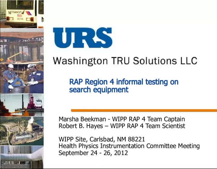
1. RAP Region 4 informal testing on search equipment Marsha Beekman - WIPP RAP 4 Team Captain Robert B. Hayes WIPP RAP 4 Team Scientist WIPP Site, Carlsbad, NM 88221 Health Physics Instrumentation Committee Meeting September 24 - 26, 2012
2. Introduction Purpose was to test overall performance for search equipment based on field conditions. Intended to support team captain, leader, and scientist determinations for coupling equipment with particular missions.
3. FACTORS Factors folded into evaluation were interface and interpretation of instrument response. Conditions were windy and not compensated for in user interface (what you see is what you get) in outdoor clear conditions. Direct sunlight may have caused reading difficulty on some displays Users allowed to continually look at instrument if vibration alarms too difficult to discriminate while walking.
4. Caveats We do not claim all other users will get identical results. Our results are approximate at best. Field conditions could substantially change the results of this test. Instruments requiring continual visual monitoring may not be consistent with some mission parameters. Each user came up with their own criteria
5. Caveats (cont.) Results were generated by less than 20 experienced and trained users. Performance by users with differing amounts of training and experience could substantially change these results. Training effectiveness for individual units could substantially change these results. Weather (daylight, wind, rain etc) could substantially alter results. Only Cs137 source tested
6. PackEye Thermo Scientific Alarm - LED indication, audio or earphone Power supply NiMH Rech., 3 days Neutron detector 2 He-3 1.5x2, 2.5 atms. Gamma detector NBR 50 keV to 3 Mev/>30 cps PackEye <13 lbs.
7. HRM (Handheld Radiation Monitor) (Sensor Technology Engineering, Inc.) Alarm Single digit (G N) LED indication and audio or vibrating alarm Power supply - 3 Volt lithium (2/3A), 1month Neutron detector He-3, 8.3 atms., 0.75x7.8 Gamma detector CsI scintillator, 0.5x1.5 HRM 8.3x 2x1.2 <1 lb.
8. LRM Alarm LCD single digit (multi scaling), audio or vibrate Power supply 3 volt lithium 2/3A 8 hrs. (backlight) 24 hrs. without Neutron detector Gamma detector Not actual LRM shown
9. D-tect D-tect Systems Alarm LED, single digit Power supply 2 AA, 5,000 hrs. Neutron - None Gamma detector CsI(Na) 0.5 x 1.5 30 keV 3 MeV D-tect 3.9x 2.7x1.2 6.4 oz.
10. G-N Pager Polimaster Alarm audio and/or vibrate, dose rate/cps readout Power supply AA, 800 hrs. Neutron detector LiI(Eu) thermal to 14 MeV Gamma detector CsI(Tl) 0.06 MeV to 3 MeV Unit (without clip) 3.4 x 2.8x 1.2 8 oz.
11. Interceptor Termo Scientific Alarm LED dose rate/cps Power supply Li-Ion rechargeable battery Neutron detector He3, 8 atm., 0.5x2.6 Gamma detector CZT 0.3x0.3x0.15 25 keV to 3 MeV ID with spectrum display Interceptor 4.8x2.6x1.2 14 oz.
12. Test Configuration Track had source at 8 foot offset Source was not neutron Distance markers at 4 foot intervals out to 24 feet Users told to simply operate equipment according to their training all users experienced Source 4 ft spacing 4 ft spacing 4 ft spacing 4 ft spacing 4 ft spacing
13. Test implementation Data recorded by independent user. Not all measurements made on all instruments by all users. No attempt was made to correct for user interface or interpretation of instrument response. Data averaged over approach from both sides (instrument held on left and right sides).
14. Initial alarm performance Multiple performance metrics of interest First to alarm Last to alarm Most consistent performance (lowest ) Results show (on average) comparable initial alarm distance on all units D-Tect most consistent (reproducible) results
15. Maximum Alarm Position Important in terms of specifically identifying source position (max. response at 0). Results presented in distance from perpendicular projection of source (not total distance to source). Some configurations can promote offset maxima Interceptor best followed by the HRM, D-tect and then GN pager.
16. Alarm Clear Location Quick alarm clear can be useful for identifying source location. If alarm continues well after source closest approach, alarm utility is reduced. Overall, instruments tend to alarm after the source . Attributed to moving time window to update and pedestrian motion.
17. Discussion Users tend to prefer items which do not require continual visual readout interpretation. You need to watch where you are walking Situational awareness can be critical Instruments known to have the highest sensitivity had some performance issues due to interface and instrument interpretation. For example, wind interference or lack of recognizing a vibrating alarm effected performance results.
18. Results Subjective results were also obtained. Users overwhelmingly preferred smaller lightweight detectors. Users preferred audible alarms when attempting to monitor detector during a normal walk effort. Users could improve vibration detection if pager was worn inside the belt (rather than outside the belt). Normal friction from walking often masked vibration alarms.
19. Mission Application Considerations Initial detection sensitivity does not favor any instrument for all field conditions. In source location, maximum location was biased differently in certain instruments. Backpacks sometimes maximize late. Small pager type instruments could maximize early on opposite hip (consider two detectors). In some situations, alarm clear ability can be advantageous.
20. Metrics by the numbers Some users preferred instruments based on interface only All instruments had results within a factor of 2 on average Reproducibility was of the same order of magnitude on all instruments Instrument Initial Alarm Distance (ft) CoV Interceptor 9.8 97% GN pager 11.2 83% HRM 13.0 126% D-tect 13.9 53% LRM 14.5 110% Packeye 16.9 56%
21. Additional testing recommend Various sized sources Different radiation types and combinations Does magnitude of neutron mixing with gamma cause issues? Does mixing of gamma energies cause issues? Not in direct sunlight Requiring identical readout methods from all users
22. Conclusion Smaller pagers tend to be preferable for mission parameters. Decision makers can consider these results for future applications Difference is in the ergonomics: Size, Weight, Clip, Pouch, Backpack Alarming indicators Audible, visual, vibration
23. Thanks Special thanks to Mark Sievers for setting up the RAP meeting/training and all the RAP Region 4 members that supported this testing effort. Questions