Understanding Cylinder Head and Valve Construction for Efficient Vehicle Performance


This article explains the purpose and construction of cylinder heads and valves in vehicles, including cast iron and cast aluminum materials and related components such as coolant passages and valve operation mechanisms. It also covers overhead camshaft heads and their incorporation of camshafts, rocker arms, and followers.
- Uploaded on | 0 Views
-
 donnywillms
About Understanding Cylinder Head and Valve Construction for Efficient Vehicle Performance
PowerPoint presentation about 'Understanding Cylinder Head and Valve Construction for Efficient Vehicle Performance'. This presentation describes the topic on This article explains the purpose and construction of cylinder heads and valves in vehicles, including cast iron and cast aluminum materials and related components such as coolant passages and valve operation mechanisms. It also covers overhead camshaft heads and their incorporation of camshafts, rocker arms, and followers.. The key topics included in this slideshow are Cylinder heads, valves, construction, cast iron, cast aluminum, overhead camshaft heads, camshafts, rocker arms, followers, vehicle performance,. Download this presentation absolutely free.
Presentation Transcript
1. Cylinder Heads and Valves Cylinder Heads and Valves
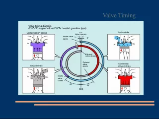
2. Cylinder Heads Cylinder Heads Purpose Purpose Construction Construction Cast Iron Cast Iron Cast Aluminum Cast Aluminum Overhead valve heads incorporate: Overhead valve heads incorporate: Valves @ related components Valves @ related components Coolant passages Coolant passages Valve operation mechanism(s) Valve operation mechanism(s)
3. Cylinder Heads Cylinder Heads Overhead camshaft heads will also incorporate: Overhead camshaft heads will also incorporate: Camshaft(s) Camshaft(s) Rocker arms or followers Rocker arms or followers
4. Camshaft Follower
5. Camshaft Follower
6. Cylinder Heads Cylinder Heads Modern designs incorporate: Modern designs incorporate: Squish area the un- concaved area in the combustion chamber designed to promote turbulence. Squish area the un- concaved area in the combustion chamber designed to promote turbulence. Quench area an area in the combustion chamber designed to cool the air/fuel mixture. Quench area an area in the combustion chamber designed to cool the air/fuel mixture.
8. Quench Area Quench Area
9. Hemispherical Cylinder Heads Hemispherical Cylinder Heads Hemi a Chrysler term for a symmetrical cylinder design. Hemi a Chrysler term for a symmetrical cylinder design. Typically valves would be positioned directly opposite in the head with a sparkplug positioned between them. Typically valves would be positioned directly opposite in the head with a sparkplug positioned between them. Modern designs my incorporate two sparkplugs. Modern designs my incorporate two sparkplugs. NOT exclusive to Chrysler! NOT exclusive to Chrysler!
12. Hemi Head
13. Cylinder Heads Cylinder Heads Surface-tovolume ratio the surface of the combustion chamber divided by the volume. Often near a 7.5:1 ratio. Surface-tovolume ratio the surface of the combustion chamber divided by the volume. Often near a 7.5:1 ratio. If the surface area is too great fuel will condense on the surface area and not ignite. If the surface area is too great fuel will condense on the surface area and not ignite.
14. Cylinder Heads Cylinder Heads Valve shrouding placing the valves close to the walls of the combustion chamber to promote turbulence. Valve shrouding placing the valves close to the walls of the combustion chamber to promote turbulence. This area also has a tendency to reduce flow at high RPM. This area also has a tendency to reduce flow at high RPM.
16. Cylinder Heads Cylinder Heads Cross flow head design the practice of placing the intake port and the exhaust port on opposite sides of the cylinder head. Cross flow head design the practice of placing the intake port and the exhaust port on opposite sides of the cylinder head.
18. Multiple Valves Multiple Valves Traditionally, combustion chambers would have one exhaust valve and one intake valve. Traditionally, combustion chambers would have one exhaust valve and one intake valve.
19. Multiple Valves Multiple Valves Three valve heads will have two intake and one exhaust valves. Three valve heads will have two intake and one exhaust valves. Allows for a greater air/fuel charge Allows for a greater air/fuel charge Lighter valves = higher RPM Lighter valves = higher RPM Greater turbulence generated Greater turbulence generated
20. Multiple Valves Multiple Valves Four valves per cylinder two exhaust and two intake valves. Four valves per cylinder two exhaust and two intake valves. Pentroof design each pair of valves are inline Pentroof design each pair of valves are inline Hemispherical design each valve is on its own axis. Hemispherical design each valve is on its own axis. Allows for center placement of the sparkplug. Allows for center placement of the sparkplug.
21. Pentroof Design
22. Hemispherical Design Hemispherical Design
23. Intake - Exhaust Ports Intake - Exhaust Ports The passageways in the cylinder head that lead to/from the combustion area. The passageways in the cylinder head that lead to/from the combustion area. Intake: Intake: Larger ports = more airflow Larger ports = more airflow Smaller ports = better velocity for low RPM operation Smaller ports = better velocity for low RPM operation Longer ports = better atomization on carb and TBI Longer ports = better atomization on carb and TBI Shorter ports = denser A/F charge Shorter ports = denser A/F charge
24. Coolant Passages Coolant Passages Coolant travels through the cylinder head from the engine block. Coolant travels through the cylinder head from the engine block. Cylinder head gaskets may be designed to restrict coolant flow rate. Cylinder head gaskets may be designed to restrict coolant flow rate. Often a source for corrosion and leakage. Often a source for corrosion and leakage.
26. Blown Head Gasket
27. Cylinder Head Removal Cylinder Head Removal All aluminum cylinder heads should be removed with a reverse torque procedure. All aluminum cylinder heads should be removed with a reverse torque procedure.
28. Cylinder Head Resurfacing Cylinder Head Resurfacing Heads should be checked in five places for warpage, distortion, bends or twists. Heads should be checked in five places for warpage, distortion, bends or twists. Check manufacturers specifications, maximum tolerances usually around .004. Check manufacturers specifications, maximum tolerances usually around .004.
29. Checking for cylinder Warpage Checking for cylinder Warpage
30. Valve Guides Valve Guides The bore in the cylinder head that supports and controls lateral valve movement. The bore in the cylinder head that supports and controls lateral valve movement. Often integral on cast iron heads Often integral on cast iron heads Always an insert on aluminum heads Always an insert on aluminum heads
31. Valve Guides Valve Guides Steel insert on aluminum heads Steel insert on aluminum heads
32. Valve Guides Bore Valve Guides Bore
33. Valve Stem To Guide Clearance Valve Stem To Guide Clearance Always check manufacturers specs Always check manufacturers specs Intake valve will typically be .001 to .003 Intake valve will typically be .001 to .003 Exhaust valve will typically be .002 to .004 Exhaust valve will typically be .002 to .004 The exhaust valve stem clearance will generally be greater due to the higher operating temperatures. The exhaust valve stem clearance will generally be greater due to the higher operating temperatures.
34. Valve Guide Wear Valve Guide Wear Guides often wear bell- mouthed due to rocker movement Guides often wear bell- mouthed due to rocker movement
35. Valve Guide Wear Valve Guide Wear Guides are checked in 3 locations Guides are checked in 3 locations With a small-hole gauge then measured with a micrometer With a small-hole gauge then measured with a micrometer Or checked with a small bore gauge Or checked with a small bore gauge
36. Valve Stem To Guide Clearance Dial Indicator Method Valve Stem To Guide Clearance Dial Indicator Method The valve is lifted off its seat to its maximum lift, locked into place and then checked with a dial indicator. The valve is lifted off its seat to its maximum lift, locked into place and then checked with a dial indicator. This method does not give the clearance directly and must be compared to specs. This method does not give the clearance directly and must be compared to specs. The valve is lifted off its seat to its maximum lift, locked into place and then checked with a dial indicator. The valve is lifted off its seat to its maximum lift, locked into place and then checked with a dial indicator. This method does not give the clearance directly and must be compared to specs. This method does not give the clearance directly and must be compared to specs.
37. Valve Stem Wear Valve Stem Wear Measured with a micrometer at three separate locations. Measured with a micrometer at three separate locations.
38. Valve Stem To Guide Clearance Correction Valve Stem To Guide Clearance Correction Oversized Valve Stems the guide is reamed to accept a larger stem. Oversized Valve Stems the guide is reamed to accept a larger stem. Must use a valve with an oversized stem. Must use a valve with an oversized stem. Reduced flow rate Reduced flow rate
39. Valve Stem To Guide Clearance Correction Valve Stem To Guide Clearance Correction Valve guide Knurling a tool is driven into the guide that displaces metal thus reducing the inside diameter of the guide. (p. 340-341) Valve guide Knurling a tool is driven into the guide that displaces metal thus reducing the inside diameter of the guide. (p. 340-341) The guide is then reamed to attain proper clearance The guide is then reamed to attain proper clearance Not recommended for clearances +.006 Not recommended for clearances +.006
40. Valve Stem To Guide Clearance Correction Valve Stem To Guide Clearance Correction Valve guide Knurling a tool is driven into the guide that displaces metal thus reducing the inside diameter of the guide. (p. 340-341) Valve guide Knurling a tool is driven into the guide that displaces metal thus reducing the inside diameter of the guide. (p. 340-341) The guide is then reamed to attain proper clearance The guide is then reamed to attain proper clearance Not recommended for clearances +.006 Not recommended for clearances +.006
41. Valve Stem To Guide Clearance Correction Valve Stem To Guide Clearance Correction Valve guide replacement (insert) the old guide is driven out and a replacement guide is driven in. Valve guide replacement (insert) the old guide is driven out and a replacement guide is driven in. The guide may require reaming to achieve proper stem to guide clearance. The guide may require reaming to achieve proper stem to guide clearance.
42. Valve Stem To Guide Clearance Correction Valve Stem To Guide Clearance Correction Valve Guide Inserts (integral) the old guide is drilled oversized and inserts are installed. Valve Guide Inserts (integral) the old guide is drilled oversized and inserts are installed. Pressed fit Pressed fit May be steel or bronze May be steel or bronze
43. Valve & Seat Service Valve & Seat Service
44. Intake & Exhaust Valves Intake & Exhaust Valves Automotive valves are of a poppet valve design. Automotive valves are of a poppet valve design.
45. Valve Materials Valve Materials Stainless steel Stainless steel May be aluminized to prevent corrosion May be aluminized to prevent corrosion Aluminum Aluminum Hardened valve tips and faces Hardened valve tips and faces Stellite (nickle, chromium and tungsten) valve tips and faces Stellite (nickle, chromium and tungsten) valve tips and faces Stellite is non-magnetic Stellite is non-magnetic
46. Valve Materials Valve Materials Sodium-filled a hollow stem filled with a metallic sodium that turns to liquid when hot (heat dissipation). Sodium-filled a hollow stem filled with a metallic sodium that turns to liquid when hot (heat dissipation). Exhaust valves are largely comprised of a chromium material (anti-oxidant) with nickel, manganese and nitrogen added. Exhaust valves are largely comprised of a chromium material (anti-oxidant) with nickel, manganese and nitrogen added. May be heat-treated May be heat-treated May be of a two-piece design May be of a two-piece design
47. Sodium Filled Valve Sodium Filled Valve
48. Intake & Exhaust Valves Intake & Exhaust Valves Valves are held into place by a retainer and keeper. Valves are held into place by a retainer and keeper. Aluminum heads will have a separate spring seat (iron heads will have integral seats) Aluminum heads will have a separate spring seat (iron heads will have integral seats)
49. Valve Seats Valve Seats Integral seats cast iron heads induction-hardened to prevent wear Integral seats cast iron heads induction-hardened to prevent wear Valve seat inserts typically aluminum heads hardened seats are pressed into the heads Valve seat inserts typically aluminum heads hardened seats are pressed into the heads
50. Valve Inspection Valve Inspection Valve tips should not be mushroomed Valve tips should not be mushroomed Most valve damage is due to excessive heat or is debris forged. Most valve damage is due to excessive heat or is debris forged. Replace any valve that appears (355- 357) Replace any valve that appears (355- 357) Burnt Burnt Cracked Cracked Stressed Stressed Necked Necked
54. Valve Springs Valve Springs A spring winds-up as it is compressed this causes the valve to rotate. A spring winds-up as it is compressed this causes the valve to rotate. May have inside dampers to control vibration. May have inside dampers to control vibration. Springs are camshaft specific. Springs are camshaft specific. Squareness (+ (-) .060) Squareness (+ (-) .060) Spring free height (+ (-) .060) Spring free height (+ (-) .060) Compressed force (+ (-) 10%) Compressed force (+ (-) 10%) Valve open Valve open Valve closed Valve closed
56. Valve Spring Tester Valve Spring Tester
57. Valve Reconditioning Valve Reconditioning The stem is lightly chamfered to insure proper fit in the valve grinder. The stem is lightly chamfered to insure proper fit in the valve grinder. The face of the valve is reground using a valve grinder. (45 or 30 degrees typical). The face of the valve is reground using a valve grinder. (45 or 30 degrees typical). Interference angle the practice of grinding the face 1degree less than the seat angle. Interference angle the practice of grinding the face 1degree less than the seat angle. The valve must retain its margin area. The valve must retain its margin area. the stem should be ground the value that the face was ground with nonadjustable rockers. the stem should be ground the value that the face was ground with nonadjustable rockers.
58. Valve Seat Reconditioning Valve Seat Reconditioning The angle of the valve seat is reconditioned. The angle of the valve seat is reconditioned. Often 3 stage (triple- angle) to promote flow and overhang. Often 3 stage (triple- angle) to promote flow and overhang. May be done with seat stones May be done with seat stones May also be done with a SERDI type set-up where the 3 angles are cut with one cutting tip. May also be done with a SERDI type set-up where the 3 angles are cut with one cutting tip.
59. Valve Lapping Valve Lapping The use of valve compound and a suction cup stick to establish a pattern The use of valve compound and a suction cup stick to establish a pattern May be done to freshen the seat and face areas May be done to freshen the seat and face areas Also used to check the contact pattern while cutting valve seats Also used to check the contact pattern while cutting valve seats All compound must be removed prior to service All compound must be removed prior to service
60. Valve Seals Valve Seals Valve Seals are designed to allow sufficient lubrication of the valve stem/guide and also control oil consumption. Valve Seals are designed to allow sufficient lubrication of the valve stem/guide and also control oil consumption. Umbrella seals hold tightly onto the valve stem (p.378) Umbrella seals hold tightly onto the valve stem (p.378) Positive valve stem seals hold tightly onto the guide Positive valve stem seals hold tightly onto the guide O-rings controls oil between the spring and retainer O-rings controls oil between the spring and retainer
61. Valve Seals Valve Seals
62. Checking Installed Height Checking Installed Height If a valve seat and face are cut the valve will sit lower in the head. If a valve seat and face are cut the valve will sit lower in the head. The result is that the stem will sit higher on the top of the head. The result is that the stem will sit higher on the top of the head. This will cause the springs to have improper tension. This will cause the springs to have improper tension. Installed height is measured and shims are added under the spring to compensate. Installed height is measured and shims are added under the spring to compensate.