Filters in Signal Processing

This article discusses the different types of filters, including lowpass, highpass, bandpass, and notch filters. It also covers the characteristics of real world and ideal filters, as well as the transfer function rules that govern them.
- Uploaded on | 0 Views
-
 fellaini
About Filters in Signal Processing
PowerPoint presentation about 'Filters in Signal Processing'. This presentation describes the topic on This article discusses the different types of filters, including lowpass, highpass, bandpass, and notch filters. It also covers the characteristics of real world and ideal filters, as well as the transfer function rules that govern them.. The key topics included in this slideshow are Filters, Signal Processing, Cutoff Frequency, Bandwidth, Transfer Function Rules,. Download this presentation absolutely free.
Presentation Transcript
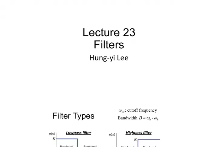
1. Lecture 23 Filters Hung-yi Lee
2. Filter Types co : cutoff frequency Lowpass filter Highpass filter Bandpass filter Notch filter Bandwidth u - l
3. Real World Ideal filter
4. Transfer Function Rules Filter is characterized by its transfer function The poles should be at the left half of the s-plane. We only consider stable filter. Given a complex pole or zero, its complex conjugate is also pole or zero.
5. Transfer Function Rules Filter is characterized by its transfer function :improper filter As the frequency increase, the output will become infinity. :proper filter We only consider proper filer. The filters consider have more poles than zeros.
6. Filter Order The order of the denominator is the order of the filter. Order = n order=1 order=4 order=4
7. Outline Textbook: Chapter 11.2 Second-order Filter Highpass Filter Lowpass Filter Notch Filter Bandpss Filter First-order Filters Highpass Filter Lowpass Filter
8. First-order Filters
9. Firsr-order Filters Case 1 : 1 pole, 0 zero first order zero or first order 1 pole 0 or 1 zero Case 2 : 1 pole, 1 zero
10. Firsr-order Filters - Case 1 Pole p is on the negative real axis Magnitude decrease Phase decrease As increases Lowpass filter
11. Firsr-order Filters - Case 1 Amplitude of the transfer function of the first-order low pass filter Ideal Lowpass filter First-order Lowpass filter
12. Find cut-off frequency co of the first-order low pass filter Firsr-order Filters - Case 1 Lowpass filter At DC Find cut-off frequency co such that
13. Firsr-order Filters - Case 2 Case 2-1 : Absolute value of zero is smaller than pole Zero can be positive or negative Magnitude is proportional to the length of green line divided by the length of the blue line Low frequency |z|/|p| The low frequency signal will be attenuated If z=0, the low frequency can be completely block Not a low pass Because |z|<|p|
14. Firsr-order Filters - Case 2 Case 2-1 : Absolute value of zero is smaller than pole Magnitude is proportional to the length of green line divided by the length of the blue line High frequency The high frequency signal will pass High pass If z=0 (completely block low frequency)
15. First-order Filters - Case 2 Find cut-off frequency co of the first-order high pass filter (the same as low pass filter)
16. First-order Filters - Case 2 Case 2-2 : Absolute value of zero is larger than pole Low frequency |z|/|p| The low frequency signal will be enhanced. Neither high pass nor low pass Because |z|>|p| High frequency: magnitude is 1 The high frequency signal will pass.
17. First-order Filters Consider v in as input If v l is output If v h is output Lowpass filter Highpass filter (pole) (pole)
18. First-order Filters (pole)
19. Cascading Two Lowpass Filters
20. Cascading Two Lowpass Filters
21. Cascading Two Lowpass Filters The first low pass filter is influenced by the second low pass filter!
22. Cascading Two Lowpass Filters
23. Cascading Two Lowpass Filters
24. Second-order Filters
25. Second-order Filter Case 1: Case 2: Case 3: Must having two poles No zeros One zeros Two zeros Second order 2 poles 0, 1 or 2 zeros
26. Second-order Filter Case 1 Case 1-1 Case 1-2
27. Second-order Filter Case 1 As increases The magnitude monotonically decreases. Decrease faster than first order low pass Case 1-1 Real Poles The magnitude is
28. Second-order Filter Case 1 Case 1-2 Complex Poles As increases, 1. Increase The magnitude is l 1 decrease first and then increase. What will happen to magnitude? l 2 always decrease 2. Decrease 3. Increase, then decrease 4. Decrease, then increase
29. Second-order Filter Case 1 Case 1-2 Complex Poles 1. Increase What will happen to magnitude? 2. Decrease 3. Increase, then decrease 4. Decrease, then increase If > d l 1 and l 2 both increase. The magnitude must decrease.
30. Second-order Filter Case 1 Case 1-2 Complex Poles Minimize Maximize the magnitude When < d
31. Second-order Filter Case 1 Minimize Minimize (maximize)
32. Second-order Filter Case 1 Lead to maximum The maxima exists when Peaking No Peaking Peaking
33. Second-order Filter Case 1 Lead to maximum The maxima exists when Peaking Assume
34. Second-order Filter Case 1 For complex poles
35. Second-order Filter Case 1 Q times of DC gain Q times
36. Second-order Filter Case 1 Lead to maximum For complex poles
37. Second-order Filter Case 1 Lead to maximum Lead to maximum The maximum exist when The maximum value is
38. Second-order Filter Case 1 (No Peaking) Case 1-2 Complex Poles Case 1-1 Real Poles Which one is considered as closer to ideal low pass filter?
39. Complex poles Peaking (Butterworth filter)
40. Butterworth Cut-off Frequency 0 is the cut-off frequency for the second-order lowpass butterworth filter (Go to the next lecture first)
41. Second-order Filter Case 2 Case 2 : 2 poles and 1 zero Case 2-1 : 2 real poles and 1 zero
42. Second-order Filter Case 2 Case 2 : 2 poles and 1 zero Case 2-1 : 2 real poles and 1 zero Bandpass Filter flat
43. Case 2-2 : 2 complex poles and 1 zero Second-order Filter Case 2 Zero Two Complex Poles + -40dB +20dB
44. Case 2-2 : 2 complex poles and 1 zero Second-order Filter Case 2 Zero Two Complex Poles + -40dB +20dB -40dB -20dB -20dB +20dB
45. Case 2-2 : 2 complex poles and 1 zero Second-order Filter Case 2 Zero Two Complex Poles + -40dB +20dB -20dB +20dB Bandpass Filter Highly Selective
46. Bandpass Filter Bandpass filter: 2 poles and zero at original point bandpass filter Bandwidth B = r - l B
47. Bandpass Filter Bandpass filter: 2 poles and zero at original point Find the frequency for the maximum amplitude
48. Bandpass Filter Transfer function of bandpass filter is maximized when 0 is center frequency
49. Bandpass Filter - Bandwidth B Four answers? Pick the two positive ones as l or r
50. Bandpass Filter - Bandwidth B Q is called quality factor Q measure the narrowness of the pass band
51. Second-order Filter Case 3
52. Second-order Filter Case 3
53. Second-order Filter Case 3
54. Second-order Filter Case 3
55. Thank you!
56. Higher order filter Buttorworth Notch filter for humming Different kinds of filter: active, passive
57. Radio Amplifier P1562
60. Suppose this band-stop filter were to suddenly start acting as a high- pass filter. Identify a single component failure that could cause this problem to occur: If resistor R 3 failed open, it would cause this problem. However, this is not the only failure that could cause the same type of problem!
61. Giutar capacitor https://www.youtube.com/watch?v=3I62Xfhts 9k
62. Algorithmic implementation wiki
63. High pass They are used as part of an audio crossover to direct high frequencies to a tweeter while attenuating bass signals which could interfere with, or damage, the speaker. When such a filter is built into a loudspeaker cabinet it is normally a passive filter that also includes a low-pass filter for the woofer and so often employs both a capacitor and inductor (although very simple high-pass filters for tweeters can consist of a series capacitor and nothing else).
64. 64 Any second-order bandpass filter may be described by Where quality factor: the network is underdamped when < 0 or Q > : damping coefficient
65. 65 The transfer function of a second-order notch filter is The notch effect comes from the quadratic numerator The notch width is B = O / Q
66. 66 Table 11.3 Simple Filter Type Transfer Function Properties Lowpass Highpass Bandpass Notch
67. Example 11.6 Design of a Bandpass Filter 67 bandpass filter: L = 1 mH, R w = 1.2 , C = ?, R = ? frequency: 20kHz 250Hz
69. From Wiki Butterworth filter maximally flat in passband and stopband for the given order Chebyshev filter (Type I) maximally flat in stopband, sharper cutoff than Butterworth of same order Chebyshev filter (Type II) maximally flat in passband, sharper cutoff than Butterworth of same order Bessel filter best pulse response for a given order because it has no group delay ripple Elliptic filter sharpest cutoff (narrowest transition between pass band and stop band) for the given order Gaussian filter minimum group delay; gives no overshoot to a step function.
70. Filter A filter is a circuit that is designed to pass signals with desired frequencies and reject the others . Magnitude ratio Filter Only input signal at these frequencies can pass
71. Loudspeaker for home usage with three types of dynamic drivers 1. Mid-range driver 2. Tweeter 3. Woofers
73. Second Order Lowpass Filter Compare with 1 st order low pass filter As the frequency increases, the amplitude ratio drops faster than 1 st order low pass filter
74. Firsr-order Filters - Case 1 |p| is the cut-off frequency Larger cut-off frequency Smaller cut-off frequency Lowpass filter
75. Firsr-order Transfer Function - Case 2 Highpass? Lowpass? Both possible? Absolute value of pole is equal to zero Positive zero can cause phase shift Magnitude is the length of green line divided by the length of the blue line All pass filter Phase is the angle of the green minus the negative one
76. First Order Lowpass Filter Maximum: Cut-off Frequency co :
77. Cut off frequency
78. 60Hz Hum
79. First-order Filters Are there anything wrong? The highpass and lowpass filters have the same cut- off frequency.