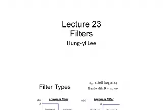
Application of Linear Phase Digital Crossover Filters to Pair Wise Symmetric Multi Way Loudspeakers

This paper discusses the use of linear phase digital crossover filters for controlling off-axis frequency response in multi-way loudspeakers. The authors present a new design technique for controlling low and high frequency responses and varying design parameters, along with implementation examples.
- Uploaded on | 0 Views
-
 jaidyn
About Application of Linear Phase Digital Crossover Filters to Pair Wise Symmetric Multi Way Loudspeakers
PowerPoint presentation about 'Application of Linear Phase Digital Crossover Filters to Pair Wise Symmetric Multi Way Loudspeakers'. This presentation describes the topic on This paper discusses the use of linear phase digital crossover filters for controlling off-axis frequency response in multi-way loudspeakers. The authors present a new design technique for controlling low and high frequency responses and varying design parameters, along with implementation examples.. The key topics included in this slideshow are Loudspeakers, Digital Crossover Filters, Linear Phase, Multi-way, Off-axis frequency response,. Download this presentation absolutely free.
Presentation Transcript
1. UH 07-09-16 page: 1 / 22 22. Sept. 2007 32 nd Intl. AES Conference DSP for Loudspeakers Hillerod, Denmark Application of Linear-Phase Digital Crossover Filters to Pair-Wise Symmetric Multi-Way Loudspeakers Part 1: Control of Off-Axis Frequency Response ULRICH HORBACH Harman Consumer Group, Northridge, California, USA D. B. (DON) KEELE, JR. Harman/Becker Automotive Systems, Martinsville, Indiana, USA
2. UH 07-09-16 page: 2 /22 Outline Traditional Crossover Alignments New Design Technique basic design control of low- and high frequency responses variation of design parameters Implementation examples: 3,4,6 - way filter approximation driver equalization baffle diffraction effects
3. UH 07-09-16 page: 3 /22 Traditional Crossover Alignments asymmetric vs. symmetric compute frequency responses using circular piston models goal: smooth off-axis responses => constant directivity
4. UH 07-09-16 page: 4 /22 Traditional (and new) Crossover Alignments
5. UH 07-09-16 page: 5 /22 Traditional Crossover Alignments 3 rd order BW with inverted midrange vertical 045 above/ below tweeter axis/ symmetric layout
6. UH 07-09-16 page: 6 /22 Traditional Crossover Alignments 4 th order Linkwitz not strictly symmetric because of woofer no flat off-axis responses
7. UH 07-09-16 page: 7 /22 Traditional Crossover Alignments 2 nd order constant voltage works quite well in the symmetric case
8. UH 07-09-16 page: 8 /22 Traditional Crossover Alignments Lowpass n=800 T=n/2 + Lowpass n=800 T=n/2 + bass mid high - - digital FIR crossover latency 16msec
9. UH 07-09-16 page: 9 /22 Traditional Crossover Alignments n=800 but still not perfect time smearing likely with effects present that cause non-ideal acoustic sum symmetric layout not applicable
10. UH 07-09-16 page: 10 /22 New Technique Basic Design Sound pressure of two monopole pairs at point P, crossed over using a filter pair with frequency responses w 1 , and (1-w 1 ):
11. UH 07-09-16 page: 11 /22 New Technique Basic Design Prescribe an attenuation a at an off-axis angle : Compute the crossover function: Setting yields the frequencies where the lowpass reaches zero, that are called critical frequencies
12. UH 07-09-16 page: 12 /22 New Technique Basic Design 6-way design example crossover frequencies result from driver location data and prescribed attenuation at desired angle max. two pairs of transducers are active at a given frequency point
13. UH 07-09-16 page: 13 /22 New Technique Control of Low Frequency Responses the frequency response below the lowest critical frequency is that of a pair of monopoles a 0 (f) , approaching one at DC prescribe a transitional frequency response a 1 (f) using a spline function ( M way design)
14. UH 07-09-16 page: 14 /22 New Technique Control of High Frequency Responses one-parameter crossover filter optimization x(n) per frequency point n includes a measured tweeter magnitude response H TW minimize n errors at n frequency points for k angles, with
15. UH 07-09-16 page: 15 /22 New Technique: Variation of Design Parameters attenuation at an arbitrary angle is the same at all critical frequency points 6-way design 0(5 ) 90 shown a) =80 , a=-20dB b) =60 , a=-12dB c) =60 , a=-30dB d) =45 , a=-6dB
16. UH 07-09-16 page: 16 /22 Implementation examples: 3/ 4-way shown 05 4 5 x=[.3, .075] =45 , a=-4.5dB f c = 340/ 1500 Hz x=[.4, .16, .06] a=60 , a=-4.5dB f c = 160/ 500/ 1700 Hz
17. UH 07-09-16 page: 17 /22 Implementation examples: 6-way
18. UH 07-09-16 page: 18 /22 Implementation examples: 6-way shown 05 4 0 x=[.7 .45 .22 .11 .048] =40 , a=-9dB f c = 160/ 300/ 600/ 1250/ 3200 Hz =40 , a=-2dB f c = 90/ 160/ 320/ 660/ 1600 Hz
19. UH 07-09-16 page: 19 /22 Implementation: Filter approximation and driver EQ H cross is real-valued (zero-phase) in this example f s =6kHz, n=128 no steep transition band => low filter degrees are possible
20. UH 07-09-16 page: 20 /22 Implementation: Filter approximation and driver EQ Measured driver impulse response FIR crossover-EQ impulse response resulting acoustic impulse response
21. UH 07-09-16 page: 21 /22 Implementation: Baffle diffraction effects
22. UH 07-09-16 page: 22 /22 Implementation: Baffle diffraction effects angle-dependent effect => equalization is not advisable! with cardboard cover Diffraction caused by woofer cavities
23. UH 07-09-16 page: 23 /22 Final remarks we presented a new class of digital crossover filters that allow the design of perfect multiway speaker systems attention needs to be paid to effects that have previously been considered second order, like baffle diffraction caused by adjacent drivers what has really happened in the loudspeaker industry over 30 years? See M. Tanaka et al, 63. AES convention, Los Angeles 1979 An Approach to the Standard Sound Transducer