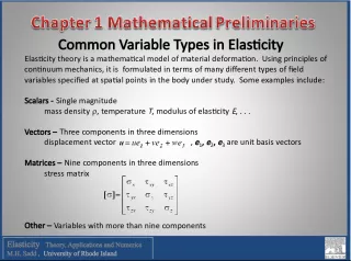
Comparison of Common Element Types in 3D Finite Element Modeling

This study aims to develop a better understanding of 3D stress analysis through the creation of a 3D FEM Matlab code. The accuracy of two different element types, linear tetrahedral and tri-linear hexahedral, will be compared, and the patch test will be used for code verification.
- Uploaded on | 0 Views
-
 jaydawalter
About Comparison of Common Element Types in 3D Finite Element Modeling
PowerPoint presentation about 'Comparison of Common Element Types in 3D Finite Element Modeling'. This presentation describes the topic on This study aims to develop a better understanding of 3D stress analysis through the creation of a 3D FEM Matlab code. The accuracy of two different element types, linear tetrahedral and tri-linear hexahedral, will be compared, and the patch test will be used for code verification.. The key topics included in this slideshow are 3D FEM, stress analysis, element types, patch test, Matlab code,. Download this presentation absolutely free.
Presentation Transcript
1. 3D Finite Element Modeling: A comparison of common element types and patch test verification BY: RACHEL SORNA AND WILLIAM WEINLANDT
2. Objectives Develop a sound understanding of 3D stress analysis through derivation, construction, and implementation of our own 3D FEM Matlab Code. Compare the accuracy of two different element types mentioned in class Linear Tetrahedral Tri-Linear Hexahedral Understand and utilize the patch test as a means of verifying our code and element modeling
3. 3D FEM Code Attempt #1 Conversion from 2DStressAnalysis Code Can you guess what loading scheme created the deformation on the right? Answer: Uniform traction of 1000N/m2 along the top boundary
4. 3D FEM Code Attempt #2 From Scratch SUCCESS!
5. Major Parts of Code Construction Addition of third dimensional variable, zeta Manual generation of meshes and defining elements and corresponding nodes 3D Elasticity matrix 3D Transformation matrix Defining solid elements and corresponding boundary surface elements Shape Functions (N matrix) Shape Function Derivatives (B Matrix) Gauss points and weights Determining which element face was on a given boundary
6. Linear Tetrahedral Boundary Surface Element Solid Volume Element
7. Tri-Linear Hexahedral Boundary Surface Element Solid Volume Element
8. Patch Test: Code and Element Verification Block Dimensions: Height: 5m Width: 5m Depth: 5m Material Properties: E: 200GPa : .3 Two simple, yet effective tests were done: fixed displacement and fixed traction Test Subject: A simple Cube Hexahedral Meshing Tetrahedral Meshing
9. Fixed Displacement Test Element Type Mesh Fineness Tetrahedral Hexahedral Coarse (48/64) 3.6e-3 7.56e-4 Moderate (750/729) 1.06e-3 2.50e-5 Fine (3000/3375) 3.06e-4 6.25e-6 Fixed displacement of .0001 was applied in the negative Z-direction. The following analytical solution gives a stress value of 4MPa throughout the cube: Table 1. Normalized L2 Norm Error values for tetrahedral and hexahedral elements for varying degrees of mesh fineness.
10. Fixed Traction Test Element Type Mesh Fineness Linear Tetrahedral Tri-Linear Hexahedral Coarse (24/27 ) 1.06e-2 3.69e-4 Moderate (750/729) 1.90e-3 4.62e-5 Fine (3000/3375) 3.60e-5 1.60e-5 Fixed traction of 1000N/m 2 was applied in the positive Z-direction. The following analytical solution gives a displacement value of 2.5e-8m on the top surface: Table 2. Normalized L2 Norm Error values for tetrahedral and hexahedral elements for varying degrees of mesh fineness.
11. Application A Complex Loading Scheme Counterclockwise oriented 1000N shearing surface tractions applied to the X and Y faces produced the following twisty cube. Comparison to the same loading scheme in ANSYS revealed that our model was valid for complex loading schemes as well. ANSYS Our Code
12. Convergence Plot The following plot shows the convergence of von-Mises stress for tetrahedral and hexahedral elements performed using our code as well as ANSYS for the twisty cube loading condition.
13. Current Limitations of Our Code Matlab can only handle so many elements and thus degrees of freedom before it becomes impossibly slow or runs out of memory Limitations of the variation in orientation of tetrahedral elements Limited possible geometries Linear elements only, no quadratic elements
14. Conclusions Hexahedral elements appear to more accurately model simple linear deformation problems than tetrahedral elements they also take far less time! Tetrahedral elements can be useful for complex geometries and loading conditions (rounded surfaces, sharp corners, etc.) For accurate meshing and modeling of complex multi-part geometries, mixed meshing, or using both tetrahedral and hexahedral, as well as other element types, is best! Writing your own FEM Code is a long and arduous process, but once you are done, you have an unparalelled understanding of the fundamental concepts!
15. Future Potential Applications
16. Just Meshing Around!