H.264 Intra Frame Coder System Design

This article discusses the design of a hardware architecture for a top-level H.264 Intra Frame Coder System. It covers the history and evolution of video coding standards, with a focus on the latest standard, H.264.
- Uploaded on | 4 Views
-
 manuel35
About H.264 Intra Frame Coder System Design
PowerPoint presentation about 'H.264 Intra Frame Coder System Design'. This presentation describes the topic on This article discusses the design of a hardware architecture for a top-level H.264 Intra Frame Coder System. It covers the history and evolution of video coding standards, with a focus on the latest standard, H.264.. The key topics included in this slideshow are H.264, Intra Frame Coder, video coding standard, hardware architecture, MPEG-4 Part 10,. Download this presentation absolutely free.
Presentation Transcript
1. H.264 Intra Frame Coder System Design zgr Tadizen Microelectronics Program at Sabanci University 4/8/2005
2. Introduction Hardware Arch i tectures For Intra Frame Code r Modules Top Level Intra Frame Coder Hardware H.264 Intra Frame Coder System Conclus i ons a nd Future Work OUTLINE
3. 1984 1985 1986 1988 1990 1992 1994 1996 1998 2000 2002 2004 H.262 / MPEG-2 H.264 / MPEG-4 Part 10 MPEG-1 MPEG-4 Joint ITU-T / MPEG MPEG ITU-T H.261 H.263 H.263+ H.263++ Standards Years The latest video co ding standard Developed with the collaboration of ITU-T and MPEG Includes 3 Profiles and 14 Levels H.264 VIDEO CODING STANDARD
4. Bandwidth Required (Mbps) Storage Utilization (MB) Download Time (Minutes) : MPEG-2 : MPEG-4 (ASP) : H.264 3.0 1.8 1.1 2025 1234 727 386 235 139 Coder MPEG-4 ASP H.263 HLP MPEG-2 H.264 38.62% 48.80% 64.46% H.264 VIDEO CODING STANDARD 90-minute DVD-quality movie (Download time at 700 Kbps) It Provides Significant Performance Gains Average Bit Rate Savings
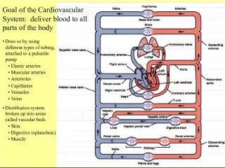
5. Reorder Entropy Coder Transform Quant Inverse Transform Inverse Quant Deblocking Filter Intra Prediction Motion Compensation Mode Decision Reconstructed Frame Reference Frame Current Frame Motion Estimation Choose Intra Mode + + + - Intra Frame Coder H.264 Encoder Block Diagram Residue Reconstruction
6. Introduction Hardware Arch i tectures For Intra Frame Code r Modules Top Level Intra Frame Coder Hardware H.264 Intra Frame Coder System Conclus i ons a nd Future Work OUTLINE
7. Transform and Quantization Algorithms Forward Transform Quantizer Inverse Transform Inverse Quantizer Hadamard Transform Inverse Hadamard Transform Residue Reconstruction VLC
8. 4x4 Forward Integer Transform 4x4 Hadamard Transform 2x2 Hadamard Transform 4x4 Inverse Integer Transform H.264 Transform Algorithm A multiply-free 4x4 integer transform is used. I t only requires additions and shifts. For 16x16 intra coded luminance blocks and for 8x8 chrominance blocks a second transform , Hadamard Transform, is applied on DC coefficients .
9. H.264 Transform Algorithm 4x4 Forward Integer Transform is applied to all the blocks except 1, 16, 17 4x4 Hadamard Transform is applied to 1 if intra 16x16 mode is selected 2x2 Hadamard Transform is applied to 16, 17
10. Register 0 stores: (x0+x4+x8+x12) Register 1 stores: (x1+x5+x9+x13) Register 2 stores: (x2+x6+x10+x14) Register 3 stores: (x3+x7+x11+x15) Pipelining Registers are used to increase the maximum clock frequency Register 4 stores the result of transform operations Transform Hardware (x0+x4+x8+x12) + (x1+x5+x9+x13) + (x2+x6+x10+x14) + (x3+x7+x11+x15) 2* (x0+x4+x8+x12) + (x1+x5+x9+x13) - (x2+x6+x10+x14) - 2* (x3+x7+x11+x15) (x0+x4+x8+x12) - (x1+x5+x9+x13) - (x2+x6+x10+x14) + (x3+x7+x11+x15) (x0+x4+x8+x12) - 2* (x1+x5+x9+x13) + 2* (x2+x6+x10+x14) - (x3+x7+x11+x15)
11. |Zij| = (|Wij|.MF + f) >> qbits, sign(Zij) = sign(Wij) |Zij| = (|Yij|.MF + 2f) >> (qbits + 1), sign(Zij) = sign(Yij ) Wij = Zij.V.2 floor(QP/6) If QP > 12 Wij = Wqij.V.2 floor(QP/6) - 2 Else Wij = [ Wqij.V + 2 1 - floor(QP/6) ] >> (2-floor (QP/6)) Quantization Hardware AC Coefficients : DC Coefficients : Inverse Quantization AC Coefficients : DC Coefficients : QP rang es from 0 to 51 . qbits = 15+floor(QP/6)
12. Transform and Quantization Hardware
13. 0.18 ASIC implementation Critical Path Delay [ ns] Gate Count Transform part of the Datapath 2.77 1978 Datapath 4.78 12773 Datapath + Control Unit 4.8 23162 Datapath + Control + Input Register File + Output Register File TQ 4.8 130505 0.18 ASIC implementation works at 210MHz and it can code 70 VGA frames per second FPGA implementation Excluding I/O Register Files Including I/O Register Files Function Generators 2497 4054 CLB Slices 1249 2027 Dffs or Latches 581 583 Block Multipliers 1 1 FPGA implementation works at 81MHz and it can code 27 VGA frames per second Hardware Implementation Results In the worst case, it takes 2500 cycles to complete the TQIQIT operations of a 4x4 block
14. Context Adaptive Variable Length Encoder Hardware 1) After prediction, transformation and quantization, blocks typically contain zeros and ones 2) The highest non-zero coefficients after the zig-zag scan are often sequences of +/-1. 3) The number of non-zero coefficients in neighbouring blocks are correlated 4) The magnitude of non-zero coefficients tends to be higher at the start
15. Datapath for 4x4 Luma Prediction Modes Controller for 16x16 Luma Prediction Modes Top Level Mode Controller Datapath for 16x16 Luma Prediction Modes Datapath for 8x8 Chroma Prediction Modes Controller for 4x4 Luma Prediction Modes Controller for 8x8 Chroma Prediction Modes Inputs from Top-Level Output MUX Prediction Buffer (384x8) Neigbouring Buffers Reconstructed Pixels Address Generation Hardwares Internal Buffers Reconstructed Pixels Intra Prediction Hardware 9 prediction modes for 4x4 luma blocks 4 prediction modes for 16x16 luma and 8x8 chroma blocks
16. Introductio n Hardware Arch i tectures For Intra Frame Code r Modules Top Level Intra Frame Coder Hardware H.264 Intra Frame Coder System Conclus i ons a nd Future Work OUTLINE
17. Input Register File SEARCH HARDWARE Output Register File CODER HARDWARE Pipelining Register File Time (cycles) 4000 Functional Units Search Hardware Coder Hardware 1st MB 2nd MB 3rd MB 4th MB 8000 12000 16000 Top Level Intra Frame Coder Hardware Level @30Mh z @40Mhz @50Mhz @60Mhz @70Mhz @80Mhz 2.0 (CIF @30 fps) 2525 3367 4208 5050 5892 6734 CIF @ 30 fp s requires processing 11800 M acroblocks per second
18. Search Hardware Reg. for 16 DC coefs. Residue 384 x 8 Current MB 384 x 8 Predicted MB Intra Pred. Hadamard Transform Residue 256 x 8 Current MB 256 x 8 Predicted MB Intra Pred. Hadamard Transform Mode Decision Luma 16x16 Chroma 8x8 Luma 4x4 Neighbors Neighbors Mode Mux QP
19. 1. Cycle: Register = 8 x 2. Cycle: Register = 16 x 3. Cycle: Register = 24 x 4. Cycle: Register = 4x4cost + 24 x 5. Cycle: Register = 16x16cost (4x4cost + 24 x ) Intra 4x4 vs Intra 16x16 Cost Comparator Mode Decision 1) Compute the cost of each 4x4 mode Select the 4x4 mode with lowest cost 2) Compute the cost of each 16x16 mode Select the 16x16 mode with lowest cost 3) Compute the cost of each 8x8 mode Select the 8x8 mode with lowest cost 4) Compare selected 4x4 and 16x16 costs and select the best mode 5) Start the coder hardware with selected mode information SATD based mode decision algorithm Cost 4x 4 Register << 3 Cost 16x16 Mux Add_sub Add/Sub Result 18 18 18 9 19 19
20. High Speed Hadamard Transform Hardware Performs SATD computation Reguires only 18 cycles for a 4x4 Block 13-bit adders/subtractors Two-stage pipeline
21. CAVLC Quant Transform Inverse Quant Inverse Transform Reconstruct Residue 384 x 9 Reg. file 384 x 16 Reg. file 16 x 16 Reg. File 384 x 8 Reconstructed MB 384 x 8 Current MB 384 x 8 Predicted MB 192 x 32 Reg. File HT IHT Intra Pred. Bitstream Coder Hardware
22. Scheduling of Intra 4x4 modes TQIQIT = 100, CAVLC = 120, Residue&Reconstruction = 18, Intra Prediction = 24 Modules Residue Intra Prediction TQIQIT CAVLC Time (cycles) 0 Reconstruction TQ IQIT TQ IQIT 24 42 86 142 160 202 246 302 320 1st Block 2nd Block Worst Case cycle counts required to complete a 4x4 block :
23. Scheduling of Intra 16x16 modes 1st Block 2nd Block 16th Block TQIQIT CAVLC Modules Time (cycles) 0 Residue Reconstruction TQ TQ TQ IQIT IQIT 920 24 42 48 86 75 130 746 HT 800 860 384 402 1040 880 Intra Prediction
24. Device Utilization s for XC2V8000 FPGA Implementation Results for H.264 Intra Frame Coder Hardware S ynthesized at 61.4 MHz and P laced & R outed at 53.8 MHz. The total equivalent gate count is 1,051,458 Resources Used Available Utilization IOs 418 1108 37.73% Global Buffers 2 16 12.50% Function Generators 21404 93184 22.97% CLB Slices 10702 46592 22.97% Dffs or Latches 3881 96508 4.02% Block RAMs 1 168 0.60% Block Multipliers 1 168 0.60%
25. Introduction Hardware Arch i tectures For Intra Frame Code r Modules Top Level Intra Frame Coder Hardware H.264 Intra Frame Coder System Conclus i ons a nd Future Work OUTLINE
26. System Overview PC is used to develop Verilog modules and debug the system Multi Ice Debugger communicates with the development board Development Board is used for testing the designed hardware Color LCD Panel is used for visual verification
27. ARM-based Development Platform Logic Tile Versatile Platform Baseboard Arm 926EJ-S Processor based Development Chip Xilinx Virtex II 8000 FPGA Xilinx Virtex II 2000 FPGA
28. Development Chip
29. ARM AMBA 2.0
30. Capturing the image in RGB format Converting the image from RGB format to YCbCr format 4:2:0 Sampling Partitioning the image into macroblocks SRAM H.264 Intra Frame Coder Hardware Reconstructing the image in raster-scan order Converting the image from YCbCr format to RGB format Displaying the reconstructed image SRAM SRAM Software Implementation Matlab and C codes are developed ARM AXD Tool is used to debug the system C codes run on ARM926EJ-S processor SRAM available on Logic Tile is used to store image data
31. ARM Development Board implements Tri-state AHB buses An AHB master is designed for reading and writing the image data to the SRAM s available on the logic tile. 2 SRAM controllers are instantiated in the design as slaves on AHM M1 and AHM M2 buses. System Arbiter controls the multiplexing Hardware Implementation
32. Verilog modules Leonardo Spectrum Netlist for XC2V8000 Xilinx Project Navigator Bitsream for XC2V8000 High Effort for Speed Bitstream Options High Effort for Speed Compiler Logic Optimizer Mapper Translator Placer Router Design Flow HDL files Synthesis Place and Route Resulting bitsream Constraints Constraints Constraints Met? Yes No Modify Modify Constraints Met? Yes No Modify
33. Introductio n Hardware Arch i tectures For Intra Frame Code r Modules Top Level Intra Frame Coder Hardware H.264 Intra Frame Coder System Conclus i ons a nd Future Work OUTLINE
34. Conclusions Transform Quant architecture is designed and verified to work at 81 MHz Mode Decision, Intra Prediction and CAVLC are integrated . Top Level design is s ynthesized at 61.4 MHz and p laced & routed at 53.8MHz. Device utilization for XC2V8000 FPGA is approximately 2 3 % with a total equivalent gate count of 1,051,458 . The H.264 Intra Frame Coder System is verified to work on an ARM Versatile Platform development board .
35. Future Work Implementing h eader generation functionality F urther verification by decoding the generated bitstream using an H.264 compliant decoder Implementing l ow-power techniques such as clock gating A dding a camera to the system for real-time video captur ing and coding Developing an ASIC implementation and fabricat ing a prototype Creating a complete H.264 video coding system by i ntegrating motion estimation, motion compensation, deblocking filter, intra vs. inter mode decision and rate control units
36. Thanks ? Questions...