Choke Mode Damped X-Band Structure for CLIC Main Linac: Collaboration between CERN and Tsinghua University

This paper discusses the collaboration between CERN and Tsinghua University in developing a choke mode damped X-band structure for the CLIC Main Linac. The paper outlines the parameters, manufacturing capability at Tsinghua, comparison with waveguide damping, wakefield damping study, and future plans.
- Uploaded on | 0 Views
-
 mareli
About Choke Mode Damped X-Band Structure for CLIC Main Linac: Collaboration between CERN and Tsinghua University
PowerPoint presentation about 'Choke Mode Damped X-Band Structure for CLIC Main Linac: Collaboration between CERN and Tsinghua University'. This presentation describes the topic on This paper discusses the collaboration between CERN and Tsinghua University in developing a choke mode damped X-band structure for the CLIC Main Linac. The paper outlines the parameters, manufacturing capability at Tsinghua, comparison with waveguide damping, wakefield damping study, and future plans.. The key topics included in this slideshow are choke mode damping, X-band structure, CLIC Main Linac, collaboration, Tsinghua University,. Download this presentation absolutely free.
Presentation Transcript
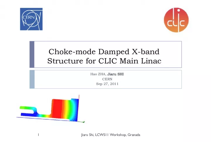
1. Choke-mode Damped X-band Structure for CLIC Main Linac Hao ZHA, Jiaru SHI CERN Sep 27, 2011 Jiaru Shi, LCWS11 Workshop, Granada 1
2. Jiaru Shi, LCWS11 Workshop, Granada Acknowledgement Collabration between CERN and Tsinghua University in China Ph.D Student visiting CERN for 6 months, ZHA Hao Manufacturing capability at Tsinghua Outline The Idea of choke-mode-damping Parameters Comparison with waveguide damping Wakefield damping study Future plans 2
3. The choke mode cavity Progress at KEK and SLAC Applications at Japanese XFEL 3
4. Radial Choke [1] Jiaru Shi, LCWS11 Workshop, Granada [1] A. Grudiev 4
5. Parameters [1] Jiaru Shi, LCWS11 Workshop, Granada Cell NDS WDS CDS1mm CDS1.5mm CDS2mm Q Cu 6825 5635(0.83) 4720(0.7) 5129(0.75) 5617(0.82) Vg / c (%) 1.32 1.2(0.9) 1.12(0.85) 1.04(0.79) 0.97(0.73) R/Q (kOhm/m) 17.8 16.1(0.91) 15.2(0.85) 14.1(0.79) 13.2(0.74) Rs (Mohm/m) 121.5 90.7 (0.75) 71.7 (0.59) 72.3 (0.59) 74.1 (0.60) E surfmax /E acc 1.93 1.93 1.93 1.93 1.93 H surfmax /E acc [mA/V] 2.5 4.0(1.6) 2.5 2.5 2.5 Pulse d T rise (K) 13 32 13 13 13 Plused T rise in first cell. @ 118MV/m 20 47 20 [1] Based on CLIC-G middle cell [2] 250 ns, 100MV/m 5
6. Advantages Lower pulsed surface heating, no magnetic field enhancement Bonding joint at low magnetic field, no problem on the chamfer Easy manufacturing, turning only Considerations Knowledge from SLAC [1] , small gap (1mm) severe breakdown / 4mm gap OK different gap size Prototype structures for high power test 6 Jiaru Shi, LCWS11 Workshop, Granada
7. Jiaru Shi, LCWS11 Workshop, Granada Damping simulation with Gdfidl/HFSS (Model in HFSS) Gap 1mm 2mm Good damping for first dipole Mode reflected by the choke, to be studied E field, fundamental mode E field of a dipole mode that is reflected by the choke Impedance and wakefield simulated in Gdfidl 7
8. EM field Jiaru Shi, LCWS11 Workshop, Granada High H, Low E Zero H, High E Fundamental mode at 12GHz High order dipole at 30GHz 8
9. EM field after detuning with bubble Jiaru Shi, LCWS11 Workshop, Granada H H E E Fundamental mode tuned back to 12GHz By changing choke-length 9
10. Smith Chart 10 A B C A B C B C Bubble,+j Bubble,+j No effect when adding to infinity Off from open point Red: fundamental mode Blue; 3h-HOM
11. Model in HFSS for optimization 11 Port 1 Port 2 Absorber in radial line absorb in the radial line: sqrt( 1-S11^2-S21^2 )
12. Radial line absorption 12 Choke reflection
13. Results of bubble-choke s 0.15m origin 20~30 Bubble- choke 20~25 WDS 6~8 13 31GHz 34GHz (in V/pC/m/mm) Push the second peak, more and more
14. Smith chart double 14 A B C A B C B double 2*z double 2*z C Red: fundamental mode Blue; 3h-HOM
15. double choke, bottle-choke 15 40GHz! 50GHz!
16. First dipole 16 s 0.15m origin 20~30 CDS 50~60 WDS 6~8 (in V/pC/m/mm)
17. Thin-neck bottle Blue: 1:1:3 bottle-choke Red: 3:1:3 thin-neck bottle-choke 17 12GHz 52GHz Narrow passband!
18. Result of thin-neck bottle 18 s 0.15 0.30 CDS- origin 20~25 10~15 CDS 2~4 0.5~0.8 WDS 6~8 1~1.5 (in V/pC/m/mm) Note: applied to Tapered structure
19. Problem of the thin neck 220MV/m electric field in the choke (@100MV/m gradient) 19
20. Impedance matching Reduced field in choke: 1:1 to gradient; as max surface field @ iris. Optimizing the depth, length, position of the step, try to match the 16G,18G mode 20
21. Absorption after impedance matching Blue: 1:1:3 bottle-choke Red: 1.5:1:3 bottle-choke with impedance matching 21
22. Result: 22 s 0.15 0.30 CDS- origin 20~25 10~15 CDS 6~8 1~2.2 WDS 6~8 1~1.5 (in V/pC/m/mm)
23. Possible design 23 Pin: 61.3MW Loaded gradient: 100MV/m CLIC-G TD24-Choke same irises Pin: 61.3MW Loaded gradient: 96MV/m
24. Summary Jiaru Shi, LCWS11 Workshop, Granada Study choke as transmission line, with smith chart Simple model in HFSS for optimization, also possible for a prototype to do RF measurement Choke mode damping with comparable result to waveguide damping Future plans Finalize the alternative RF design with choke-mode damping that could possibly replace the baseline design Propose wakefield measurement at SLAC Prototype for high power test 24
25. Thank you! Jiaru Shi, LCWS11 Workshop, Granada 25