Normal incidence analysis of simple dielectric and photonic crystal slabs

This article covers the reflection and transmission spectra for various types of slabs, including simple dielectric, photonic crystal, and Distributed Bragg mirrors. The analysis is conducted with normal incidence and includes a discussion of planewave sources and periodic boundary conditions.
- Uploaded on | 3 Views
-
 sullivan
About Normal incidence analysis of simple dielectric and photonic crystal slabs
PowerPoint presentation about 'Normal incidence analysis of simple dielectric and photonic crystal slabs'. This presentation describes the topic on This article covers the reflection and transmission spectra for various types of slabs, including simple dielectric, photonic crystal, and Distributed Bragg mirrors. The analysis is conducted with normal incidence and includes a discussion of planewave sources and periodic boundary conditions.. The key topics included in this slideshow are reflection, transmission, spectra, dielectric slab, photonic crystal slab,. Download this presentation absolutely free.
Presentation Transcript
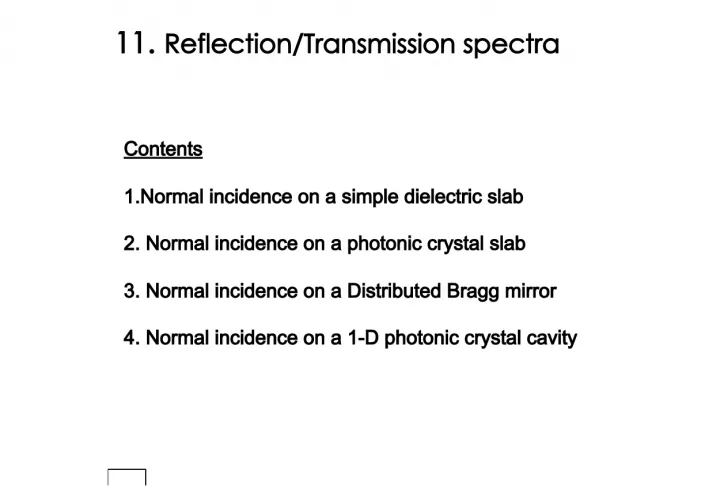
1. 11. Reflection/Transmission spectra Contents 1. Normal incidence on a simple dielectric slab 2. Normal incidence on a photonic crystal slab 3. Normal incidence on a Distributed Bragg mirror 4. Normal incidence on a 1-D photonic crystal cavity
2. Without slab With slab Planewave source Detect Slab (T=1a) 1. Simple dielectric slab
3. DD shouldnt be this much long because the simple Fabry-Perot slab does not have a high-Q resonance. As we can see from the field data, DD may be set 4000. We will not use DS in this example (1,1) may be set (0.1, 0.1). Gamma point periodic boundary condition. The use of the planewave source ensures that the result will be only for the exact kx=ky=0 point.
4. Two point detectors were set, one after the slab and the other between the planewave source and the slab
5. 1) We now have modeR.dat and modeT.dat 2) We must run another simulation in the absence of the dielectric slab. Then, we get modeR0.dat and modeT0.dat , which will be used as reference data. 3) Lets denote modeR.dat = R(t) modeT.dat = T(t) modeR0.dat = R0(t) modeT0.dat = T0(t) Now lets perform the following calculations. FT[ R(t)-R0(t) ] / FT[ R0(t) ] = Refelctance spectrum in FT[ T(t) ] / FT[ T0(t) ] = Transmission spectrum in ,where FT denotes Fourier Transformation. ** How to obtain R & T spectra (Important Node ) One must remember that the resolution of discrete FT will depend on the length of input data. We must add null values at the end of all ***.dat file before performing FT. I typically make the entire length of the input data file to be about 1 million (should be 2 n format for accurate result)
6. Result
7. 2. Square lattice photonic crystal slab
8. In this example, DD should be carefully chosen. The 2-D photonic-crystal slab may contain very high-Q resonances (See the Fans paper) We will not use DS in this example You cannot change this (1,1)
9. Two point detectors were set, one after the slab and the other between the planewave source and the slab
10. Result
11. 3. Distributed Bragg Reflector 20 pairs of AlAs/GaAs Target wavelength = 950 nm GaAs AlAs Grid resolution z = 2.5 nm Periodic boundary condition for x-y directions z Planewave source PML PML
12. In this example, DD should be carefully chosen. The time required to reach the steady-state could be longer than you initially thought. We will not use DS in this example You can change this as 0.1
13. In this example, we will only get reflectance spectrum
14. Result
15. Accuracy Analytic expression (at the Bragg condition) Exact FDTD 0.832424 0.83231 0.947996 0.94795 0.991636 0.99162 10 14 20 m Errors less than 1 part per 10,000 !
16. 4. 1-D photonic-crystal cavity GaAs AlAs A cavity is formed by the two Bragg mirrors
20. Result
21. Single excitation (950nm) Ey field 3 QWs