MEBT Design Considerations for Controlling Emittance Growth

The Medium Energy Beam Transport (MEBT) system operates at relatively low beam energies, where space charge forces can significantly affect beam dynamics. To prevent emittance growth,
- Uploaded on | 0 Views
-
 andrej
About MEBT Design Considerations for Controlling Emittance Growth
PowerPoint presentation about 'MEBT Design Considerations for Controlling Emittance Growth'. This presentation describes the topic on The Medium Energy Beam Transport (MEBT) system operates at relatively low beam energies, where space charge forces can significantly affect beam dynamics. To prevent emittance growth,. The key topics included in this slideshow are . Download this presentation absolutely free.
Presentation Transcript
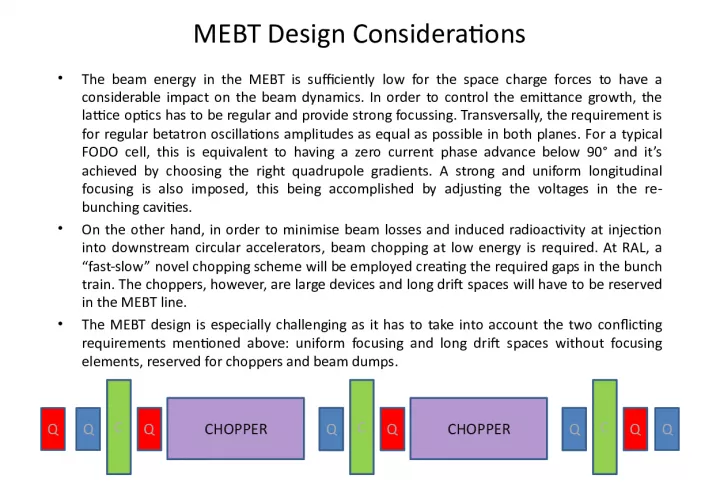
Slide1MEBT Design Considerations• The beam energy in the MEBT is sufficiently low for the space charge forces to have a considerable impact on the beam dynamics. In order to control the emittance growth, the lattice optics has to be regular and provide strong focussing. Transversally, the requirement is for regular betatron oscillations amplitudes as equal as possible in both planes. For a typical FODO cell, this is equivalent to having a zero current phase advance below 90° and it’s achieved by choosing the right quadrupole gradients. A strong and uniform longitudinal focusing is also imposed, this being accomplished by adjusting the voltages in the re- bunching cavities. • On the other hand, in order to minimise beam losses and induced radioactivity at injection into downstream circular accelerators, beam chopping at low energy is required. At RAL, a “fast-slow” novel chopping scheme will be employed creating the required gaps in the bunch train. The choppers, however, are large devices and long drift spaces will have to be reserved in the MEBT line. • The MEBT design is especially challenging as it has to take into account the two conflicting requirements mentioned above: uniform focusing and long drift spaces without focusing elements, reserved for choppers and beam dumps. Q Q C Q Q Q C Q C Q CHOPPER CHOPPER Q
Slide2Possible MEBT Schemes• Scheme 1 represents the preferred design for the FETS project. The front and the end matching sections are similar and consist of a two doublet quadrupole configuration and a 324 MHz CCL-type re-bunching cavity. The choppers are arranged symmetrically, each followed by a dedicated beam dump and a defocusing quadrupole. The defocusing quadrupoles are used to amplify the deflection given by the choppers, thus reducing the required voltage on the chopper plates. Fast Chopper Slow Chopper Beam Dumps Quadrupoles Re-bunching cavities RFQ DTL
Slide3Possible MEBT Schemes• Scheme 2 is currently being used in the ISIS upgrade linac design and it comprises of two input quadrupoles, two solenoids, two sets of asymmetric triplet quadrupoles and four 324 Mhz re-bunching cavities. The input quadrupoles are used for matching the beam from the RFQ, while the solenoids focus the beam into a ~1.5 m long drift where the two choppers are placed. This is followed by a first set of triplets, a ~1.1 m long drift section for the beam dump, and a second set of triplets to match the beam into the DTL Fast Chopper Slow Chopper Beam Dump Quadrupoles Re-bunching cavities RFQ DTL Solenoids
Slide4Possible MEBT Schemes• Scheme 3 investigates the possibility of using a more regular lattice. For this purpose, three sets of symmetric triplet quadrupoles and six re-bunching cavities are being used. They are equally spaced by long drift tube sections reserved for the two choppers and for the beam dump. Fast Chopper Slow Chopper Beam Dump Quadrupoles Re-bunching cavities RFQ DTL
Slide5MEBT + DTL• Beam tracking studies indicate that the MEBT design has a strong influence on the beam quality in the downstream accelerators (ISIS Upgrade Linac) • 3 MEBT Schemes + DTL (1 tank) , DTL: 3 – 16 MeV , 60 mA, 324 MHz – Input beam distribution: Gaussian, 50k particles, RMS Emitt x/y/z: 0.27/0.27/0.38 Pi.mm.mrad 1 DTL Tank, 60 mA, 3 -16 MeV MEBT 2 MEBT 3 MEBT 1
Slide6MEBT + DTL Beam Envelopes MEBT 1 + DTL MEBT 3 + DTL MEBT 2 + DTL
Slide7MEBT + DTL Discussion Emittance Growth DTL MEBT 1 + DTL MEBT 2 + DTL MEBT 3 + DTL MEBT (%) tr - 10.1 22.3 25.6 z - 4.5 21.7 17.3 DTL (%) tr 4 0 1.9 17 z 6.5 3.9 1.1 12 Total (%) tr 4 10.1 24.7 46.9 z 6.5 8.6 23.1 31.5 Ha lo(%) tr/z ~15 ~30 ~60 150 Emittance growth In the first design, the two long choppers create an irregular lattice for the central section of the MEBT. However, by having a symmetrical scheme, the drift lengths are reduced to ~ 0.5 m. Shorter drifts are desirable from the beam optics point of view, and by carefully choosing the quadrupole gradients, the beta functions can be kept comparable in both transverse planes. Consequently, the emittance growth and the halo development are reasonably controlled, both in the MEBT line and the DTL. For the second scheme, the chopper sections have a similar effect on the lattice. However, the reserved drift spaces are much longer (~1.5 and ~1.1 m) and as a result, the strong space charge forces will distort the beam structure more than for the first scheme, leading to a higher emittance growth. The third MEBT also includes two long drift sections (~1.1 m each) but has the advantage of a periodic lattice. However, the betatron oscillations amplitudes vary significantly in the two transverse planes and the beam quality is deteriorating rapidly.