Understanding Computer Memory and UNIVAC Console

This article discusses the characteristics of computer memory, the UNIVAC Console and CPU, and the memory hierarchy including registers, cache, main memory, magnetic disk, disk cache, magnetic tape, and optical disk.
- Uploaded on | 1 Views
-
 glinda
About Understanding Computer Memory and UNIVAC Console
PowerPoint presentation about 'Understanding Computer Memory and UNIVAC Console'. This presentation describes the topic on This article discusses the characteristics of computer memory, the UNIVAC Console and CPU, and the memory hierarchy including registers, cache, main memory, magnetic disk, disk cache, magnetic tape, and optical disk.. The key topics included in this slideshow are Computers, internal memory, external memory, UNIVAC Console, CPU, memory hierarchy, registers, cache, main memory, magnetic disk, optical disk,. Download this presentation absolutely free.
Presentation Transcript
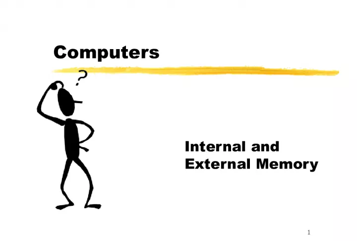
1. 1 Computers Internal and External Memory
2. 2 Characteristics of Computer Memory z Location z Capacity z Unit of transfer z Access Method z Performance z Physical Type z Organization
3. 3 UNIVAC Console and CPU
4. 4 CPUs
5. 5 Memory Hierarchy CACHE MAIN MEMORY MAGNETIC DISK | DISK CACHE MAGNETIC TAPE | OPTICAL DISK SPEED COST REGISTERS
6. 6 Capacity Units z Bit z Byte z Kilobyte z Megabyte z Gigabyte z Terabyte z b z B = 8 b z KB = 1,000 B z MB = 1,000,000 B z GB = 1,000,000,000 B z TB = 1,000,000,000,000 B
7. 7 Memory Access Method z Sequential - tape z Direct - floppy or hard disk z Random - internal memory y Dynamic (DRAM) simple, small, must be refreshed y Static (SRAM) no refresh needed z Associative - some cache
8. 8 Random Access Memory z Chips and chip technology
9. 9 Flip Flop Circuit Diagram
10. 10 Memory Cells 0/1 SELECT select cell CONTROL read or write DATA IN / SENSE input or output SELECT select cell CONTROL read or write 1
11. 11 Write to Memory COL ADDRESS BUFFER MUX REFRESH ARRAY DATA INPUT BUFFER DATA OUTPUT BUFFER A0 . . . A10 D1 . . D4 ROW ADDRESS BUFFER Read Enable Col Address Row Address Write Enable Row Address ROW ADDRESS BUFFER COL ADDRESS BUFFER Col Address MUX Write Enable DATA INPUT BUFFER
12. 12 Pin Assignments z A0 A10: address location (multiplexed) z D1 D4: data in or out z Vcc: power supply z Vss: ground z RAS: row address select z CAS: column address select z WE: write enable z OS: output enable
13. 13 Cache Operation ALU CNTL ..... BUS MAIN MEMORY CACHE
14. 14
15. 15 Cache Main Memory CPU CACHE Word Block
16. 16 Cache
17. 17 Random Access z Direct Access Storage Device (DASD) or disk drives y Optical y Magnetic
18. 18 Optical Disks (CDs)
19. 19 How CDs work
20. 20 Cylinder/Track/Block Block (Sector) Track Cylinder
21. 21 Disk Organization
22. 22 DASD Structure Read-Write Heads
23. 23 Data Storage z FAT (File Access Tables), Directories and Catalogs z Update and Delete z Fragmentation and reorganization z Blocks, Headers and Interblock Gaps
24. 24 DASD Access (PC) MAIN MEMORY DASD BUFFER CONTROLLER CPU CACHE
25. 25
26. 26 DASD Access (PC) MAIN MEMORY DASD BUFFER CONTROLLER CPU
27. 27 DASD Access (Mainframe) MAIN MEMORY DASD BUFFER CONTROLLER CPU CHANNEL
28. 28 Data Structure HEADER DATA CRC HEADER BLOCK Header written when disk is formatted Data copied into block Cyclical Redundancy Check calculated
29. 29 Controller Operation (DASD retrieval) z CPU passes parameters to registers in the controller z The controller transfers data into the card buffer z The controller checks the CRC to assure the data was copied correctly z The controller (or CPU) transfers buffered data to memory one word at a time
30. 30 Access Time: time from call until first data available z Disk Access Time = Rotational Delay + Seek Time + Transfer Time z RAM Access Time = y Refresh Time + Transfer Time
31. 31 Access Time Example z Disk Drive has y 7200 rpm = 120 rps y 8 ms average seek time y 80 MBps transfer rate z Rotational delay = 1/2*1/120 = 1/240 s = .0042 z Seek Time = 8/1,000 s = .0080 z Transfer Time = 512/80,000 s = .0064
32. 32 Time Units z Millisecond z Microsecond z Nanosecond z Picosecond z ms = 1/1000 s z s = 1/1,000,000 s z ns = 1/1,000,000,000 s z ps = 1/1,000,000,000,000 s
33. 33 Representative Times z Network speed = megabits per second z Disk transfer = megabytes per second z Disk access = milliseconds z Memory access = nanoseconds z Machine cycle = microseconds/nanoseconds
34. 34 Error Correction and Checking Add bits to a block to use for error discovery y Detection only y Detection and retransmission y Detection and recovery Check Body Header Block
35. 35 Error Detection Only (Asynchronous Transmission) * * * * * * * Parity Bit 7 Data Bits 2 7 = 128 distinct characters *
36. 36 Error Detection &Correction (Hamming Code: 4 bit word) * * * * 3 Error Checking Bits 4 Data Bits * * *
37. 37 DATA 1 1 1 0 Error Detection &Correction (Hamming Code: 4 bit word) 1 1 1 0 * * *
38. 38 PARITY (even) 1 1 1 0 1 0 0 Error Detection 1 1 1 0 1 0 0
39. 39 PARITY (even) 0 1 1 0 1 0 0 Error Correction (4 bit word) 0 1 1 0 1 0 0
40. 40 Error Correction & Detection z Error detection takes fewer bits than error correction z Longer packets take a smaller percent for correction but have more types of errors z Hammings scheme detects all errors at a high overhead cost; others may correct only single bit or double bit errors with shorter check fields
41. 41 CRC Error Checking z The transmitted messages are divided into predetermined blocks z The blocks are divided by a fixed divisor z The remainder is appended to the message
42. 42 IBM 1107 with tape drives
43. 43 Memory