The Evolution of Energy Absorption Systems for Crashworthy Helicopter Seats
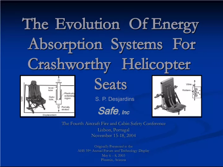

This presentation discusses the history and development of energy absorption systems for crashworthy helicopter seats. It was originally presented at the AHS 59th Annual Forum in
- Uploaded on | 1 Views
-
 jaydensingh
About The Evolution of Energy Absorption Systems for Crashworthy Helicopter Seats
PowerPoint presentation about 'The Evolution of Energy Absorption Systems for Crashworthy Helicopter Seats'. This presentation describes the topic on This presentation discusses the history and development of energy absorption systems for crashworthy helicopter seats. It was originally presented at the AHS 59th Annual Forum in. The key topics included in this slideshow are . Download this presentation absolutely free.
Presentation Transcript
Slide1The Evolution Of Energy Absorption Systems For Crashworthy Helicopter Seats The Evolution Of Energy Absorption Systems For Crashworthy Helicopter Seats The Fourth Aircraft Fire and Cabin Safety Conference The Fourth Aircraft Fire and Cabin Safety Conference Lisbon, Portugal Lisbon, Portugal November 15-18, 2004 November 15-18, 2004 Originally Presented at the Originally Presented at the AHS 59 th Annual Forum and Technology Display AHS 59 th Annual Forum and Technology Display May 6 – 8, 2003 May 6 – 8, 2003 Phoenix, Arizona Phoenix, Arizona . . S. P. Desjardins Safe , Inc
Slide2OBJECTIVE AND PURPOSE OBJECTIVE AND PURPOSE Objective – Trace Development of Energy Absorbing Systems – Early 1960’s to Present. Objective – Trace Development of Energy Absorbing Systems – Early 1960’s to Present. Purpose – Assess the Current State-of-the-Art, Identify Any Areas of Concern, and Recommend Future Efforts. Purpose – Assess the Current State-of-the-Art, Identify Any Areas of Concern, and Recommend Future Efforts.
Slide3APPROACHAPPROACH Review Review Early Work and Concepts Early Work and Concepts Process and Rationale That Lead to the Different Approaches Process and Rationale That Lead to the Different Approaches Approaches Used by the Different Suppliers Approaches Used by the Different Suppliers Present Present Advanced Concept Advanced Concept Concerns About Current Requirements Concerns About Current Requirements Conclusions Conclusions
Slide4NEED FOR CRASHWORTHY SEATS NEED FOR CRASHWORTHY SEATS Established in the Late 1950’s and Early 1960’s by AvCIR Established in the Late 1950’s and Early 1960’s by AvCIR Survivable Crash Environment was Determined Survivable Crash Environment was Determined Concluded that a Properly Restrained Occupant Could Survive the Resultant Loading in the X and Y Directions, but not in the Z Concluded that a Properly Restrained Occupant Could Survive the Resultant Loading in the X and Y Directions, but not in the Z
Slide5NEED FOR CRASHWORTHY SEATS, Cont’d NEED FOR CRASHWORTHY SEATS, Cont’d Loading in the Z Direction Exceeded Human Tolerance and Needed to be Limited Loading in the Z Direction Exceeded Human Tolerance and Needed to be Limited Approach – Support the Occupant in a Seat that would Stroke when the Load Reached the Tolerance Limit (Limit Load) Approach – Support the Occupant in a Seat that would Stroke when the Load Reached the Tolerance Limit (Limit Load)
Slide6DECELERATION – TIME RELATIONSHIPS, Z DIRECTION DECELERATION – TIME RELATIONSHIPS, Z DIRECTION
Slide7DECELERATION – TIME RELATIONSHIPS DECELERATION – TIME RELATIONSHIPS
Slide8IDEALIZED RELATIONSHIP IDEALIZED RELATIONSHIP Where: Where: S = stroke or deformation, in. S = stroke or deformation, in. G = gravitational constant (32.2 ft/sec 2 or 386.4 in. /sec 2 ) G = gravitational constant (32.2 ft/sec 2 or 386.4 in. /sec 2 ) t m = time to G m , sec. t m = time to G m , sec. G m = Maximum deceleration, G G m = Maximum deceleration, G G L = Limit-load deceleration, G G L = Limit-load deceleration, G k = constant = G L /G m k = constant = G L /G m
Slide9SEAT STROKE CALCULATION SEAT STROKE CALCULATION As an example, consider a triangular pulse representing a change in velocity of 42 ft/ per sec. with: As an example, consider a triangular pulse representing a change in velocity of 42 ft/ per sec. with: G m = 48 G G m = 48 G T m = 0.027 sec. T m = 0.027 sec. G L = 14.5 G G L = 14.5 G k = 14.5/48 = 0.30 k = 14.5/48 = 0.30 Then from the above equation : Then from the above equation : S = 11.02 in. S = 11.02 in.
Slide10 AIRFRAME STROKE CALCULATION AIRFRAME STROKE CALCULATION Where: Where: S = Stroke or distance traveled, ft. S = Stroke or distance traveled, ft. V 0 = Initial velocity, ft/sec. V 0 = Initial velocity, ft/sec. V f = Final velocity, ft/sec. V f = Final velocity, ft/sec. g = 32.2 ft/sec. 2 g = 32.2 ft/sec. 2 G = Average deceleration of airframe, 14.5 G G = Average deceleration of airframe, 14.5 G S = 1.89 ft. (or 22.67 in.) S = 1.89 ft. (or 22.67 in.)
Slide11CRASH LOAD ATTENUATOR CONCEPTS CRASH LOAD ATTENUATOR CONCEPTS Crushable Column Crushable Column Rolling Torus Rolling Torus Inversion Tube Inversion Tube Cutting or Slitting Cutting or Slitting Tube and Die Tube and Die Rolling/Flattening a Tube Rolling/Flattening a Tube Strap, Rod, or Wire Bender Strap, Rod, or Wire Bender Wire-Through-Platen Wire-Through-Platen Deformable Links Elongation of Tube, Strap, or Cable Tube Flaring Housed Coiled Cable Bar-Through-Die Hydraulic Pneumatic
Slide12FIXED LOAD ENERGY ABSORBERS (FLEA) FIXED LOAD ENERGY ABSORBERS (FLEA)
Slide13DYNAMIC OVERSHOOT DYNAMIC OVERSHOOT
Slide14FIXED LOAD DESIGN CRITERIA FIXED LOAD DESIGN CRITERIA Human tolerance is a function of time-under- load. Human tolerance is a function of time-under- load. It was determined through analysis and test that to retain a tolerable time-under-load environment, the limit load, L L , should be set at 14.5 G. It was determined through analysis and test that to retain a tolerable time-under-load environment, the limit load, L L , should be set at 14.5 G.
Slide15UH-60 BLACK HAWK ARMORED CREWSEAT, INVERSION TUBE E/A UH-60 BLACK HAWK ARMORED CREWSEAT, INVERSION TUBE E/A
Slide16EH101 FOLDABLE TROOP SEAT, WIRE BENDER E/A EH101 FOLDABLE TROOP SEAT, WIRE BENDER E/A
Slide17BELL 230/430 PILOT SEAT, CRUSHABLE COMPOSITE COLUMN E/A BELL 230/430 PILOT SEAT, CRUSHABLE COMPOSITE COLUMN E/A
Slide18FRENCH/GERMAN TIGER ARMORED CREWSEAT, METAL CUTTER E/A FRENCH/GERMAN TIGER ARMORED CREWSEAT, METAL CUTTER E/A
Slide19A129 ITALIAN ARMORED CREWSEAT, TUBE AND DIE E/A A129 ITALIAN ARMORED CREWSEAT, TUBE AND DIE E/A
Slide20BELL 230/305 MEDICAL ATTENDANT SEAT,STRAP BENDER E/A BELL 230/305 MEDICAL ATTENDANT SEAT,STRAP BENDER E/A
Slide21V-22 OSPREY TROOP SEAT, TUBE AND DIE E/A V-22 OSPREY TROOP SEAT, TUBE AND DIE E/A
Slide22VARIABLE LOAD ENERGY ABSORBERS VARIABLE LOAD ENERGY ABSORBERS Fixed Load System is Designed for the 50 th Percentile Occupant Fixed Load System is Designed for the 50 th Percentile Occupant Effective Weight of the Lightly Clad 50 th Percentile Occupant is 142.3 lb Effective Weight of the Lightly Clad 50 th Percentile Occupant is 142.3 lb Assuming a 60-lb Movable Seat Weight, the Limit Load,L L , the Load at Which the Seat is Designed to Stroke is: Assuming a 60-lb Movable Seat Weight, the Limit Load,L L , the Load at Which the Seat is Designed to Stroke is: L L = G L W teff = (14.5) (202.3) = 2,933 lb L L = G L W teff = (14.5) (202.3) = 2,933 lb
Slide23VARIABLE LOAD ENERGY ABSORBERS, Cont’d VARIABLE LOAD ENERGY ABSORBERS, Cont’d Assuming the Same 60 lb Movable Seat Weight, the Total Effective Weight Range that the Load Limiting System Must Decelerate are: Assuming the Same 60 lb Movable Seat Weight, the Total Effective Weight Range that the Load Limiting System Must Decelerate are: 5 th - percentile: 172.6 lb 5 th - percentile: 172.6 lb 95 th -percentile: 235.2 lb 95 th -percentile: 235.2 lb With a Fixed Load Energy Absorber, the Resultant Load Factors for the 95th - and 5th - Percentile Aviators are then: With a Fixed Load Energy Absorber, the Resultant Load Factors for the 95th - and 5th - Percentile Aviators are then: G L 95 th - = 2,933/235.2 = 12.6 G G L 95 th - = 2,933/235.2 = 12.6 G G L 5 th = 2,933/172.6 = 17.0 G G L 5 th = 2,933/172.6 = 17.0 G
Slide24VARIABLE LOAD E/A ADJUSTMENT RANGE VARIABLE LOAD E/A ADJUSTMENT RANGE
Slide25V-22 OSPREY ARMORED CREWSEAT, WIRE BENDER VLEA V-22 OSPREY ARMORED CREWSEAT, WIRE BENDER VLEA
Slide26UH-1Y ARMORED CREWSEAT, INVERSION TUBE VLEA UH-1Y ARMORED CREWSEAT, INVERSION TUBE VLEA
Slide27FIXED PROFILE ENERGY ABSORBERS (FPEA) FIXED PROFILE ENERGY ABSORBERS (FPEA)
Slide28BELL 230/260 PILOT SEAT, STRAP BENDER, FPEA BELL 230/260 PILOT SEAT, STRAP BENDER, FPEA
Slide29LOAD-STROKE PROFILE VS CONSTANT LOAD, MILITARY REQUIREMENTS LOAD-STROKE PROFILE VS CONSTANT LOAD, MILITARY REQUIREMENTS
Slide30UH-1Y TROOP SEAT, WIRE BENDER, FPEA UH-1Y TROOP SEAT, WIRE BENDER, FPEA
Slide31ADVANCED SYSTEMS ADVANCED SYSTEMS OBJECTIVES OBJECTIVES To Combine the Advantages of the Fixed Profile (FPEA) with those of the Variable Load (VLEA) to Produce the Variable Profile Energy Absorber (VPEA) To Combine the Advantages of the Fixed Profile (FPEA) with those of the Variable Load (VLEA) to Produce the Variable Profile Energy Absorber (VPEA) To Automatically Adjust the Load Level of the Profile to Eliminate the Possibility of Human Error in Selecting the Load To Automatically Adjust the Load Level of the Profile to Eliminate the Possibility of Human Error in Selecting the Load
Slide32OBJECTIVES, Cont’d OBJECTIVES, Cont’d To Provide all occupants With Comparable Protection Regardless of Weight, 5 th Percentile Female to 95 th Percentile Male To Provide all occupants With Comparable Protection Regardless of Weight, 5 th Percentile Female to 95 th Percentile Male
Slide33CONCLUSIONSCONCLUSIONS The Following Concepts Suggested in the Late1960’s and Early 1970’s for Use in Energy Absorbing Crashworthy Seats Have Been Developed, Incorporated into Seats and Are Now in Common Use Around the World: The Following Concepts Suggested in the Late1960’s and Early 1970’s for Use in Energy Absorbing Crashworthy Seats Have Been Developed, Incorporated into Seats and Are Now in Common Use Around the World: Inversion Tube Inversion Tube Wire Bender Wire Bender Strap Bender Strap Bender Metal Cutter Metal Cutter Tube and Die Tube and Die
Slide34CONCLUSIONS, Cont’d CONCLUSIONS, Cont’d The Evolutionary Process Has Produced: The Evolutionary Process Has Produced: Fixed Load Energy Absorbers (FLEA) Fixed Load Energy Absorbers (FLEA) Variable Load Energy Absorbers (VLEA) Variable Load Energy Absorbers (VLEA) Fixed Profile Energy Absorbers (FPEA) Fixed Profile Energy Absorbers (FPEA) Variable Profile Energy Absorbers (VPEA) Variable Profile Energy Absorbers (VPEA) An Advanced Energy Absorber Concept (AEA) An Advanced Energy Absorber Concept (AEA) Equipped Seats Have Performed Well in Helicopter Crashes. Equipped Seats Have Performed Well in Helicopter Crashes.
Slide35CONCLUSIONS, Cont’d CONCLUSIONS, Cont’d A problem Likely Exists With Certification Requirements for Civil Seats. A problem Likely Exists With Certification Requirements for Civil Seats. Efforts to Improve Efficiency Have Lead to Use of Fixed Profile Energy Absorbers. Efforts to Improve Efficiency Have Lead to Use of Fixed Profile Energy Absorbers. Performance is Sensitive to Occupant Weight and Response Characteristics. Performance is Sensitive to Occupant Weight and Response Characteristics. Civil Certification Requires Testing With Only One Size of Dummy, the 50 th Percentile. Civil Certification Requires Testing With Only One Size of Dummy, the 50 th Percentile. This Process Can Result in a Seat Tuned to the Characteristics of a Specific 50 th Percentile Dummy with disregard for its Performance with all Occupants of Different Sizes or Response Characteristics. This Process Can Result in a Seat Tuned to the Characteristics of a Specific 50 th Percentile Dummy with disregard for its Performance with all Occupants of Different Sizes or Response Characteristics.
Slide36COMPARISON OF FIXED PROFILE SHAPES COMPARISON OF FIXED PROFILE SHAPES
Slide37CONCLUSIONS, Cont’d CONCLUSIONS, Cont’d Since Systems are Now Being Developed That Take Advantage of the Unique Response Characteristics of the Test Dummy, Since Systems are Now Being Developed That Take Advantage of the Unique Response Characteristics of the Test Dummy, All Development and Certification Testing Should Include a Range of Dummy Sizes Representative of the Entire Spectrum Of Occupant Weights Expected to Use the Seat. All Development and Certification Testing Should Include a Range of Dummy Sizes Representative of the Entire Spectrum Of Occupant Weights Expected to Use the Seat. Dummies Should be Developed and Used that More Accurately Simulate the Human Response to Rapid Loading in the Z Direction. Dummies Should be Developed and Used that More Accurately Simulate the Human Response to Rapid Loading in the Z Direction.