Potentiometric Methods: A Fundamentals Overview

Potentiometric methods are electroanalytical techniques that measure the potential of electrochemical cells without any significant current flow. This overview covers the basic components of potentiometric methods, including
- Uploaded on | 5 Views
-
 oleksandr
About Potentiometric Methods: A Fundamentals Overview
PowerPoint presentation about 'Potentiometric Methods: A Fundamentals Overview'. This presentation describes the topic on Potentiometric methods are electroanalytical techniques that measure the potential of electrochemical cells without any significant current flow. This overview covers the basic components of potentiometric methods, including. The key topics included in this slideshow are . Download this presentation absolutely free.
Presentation Transcript
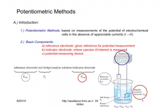
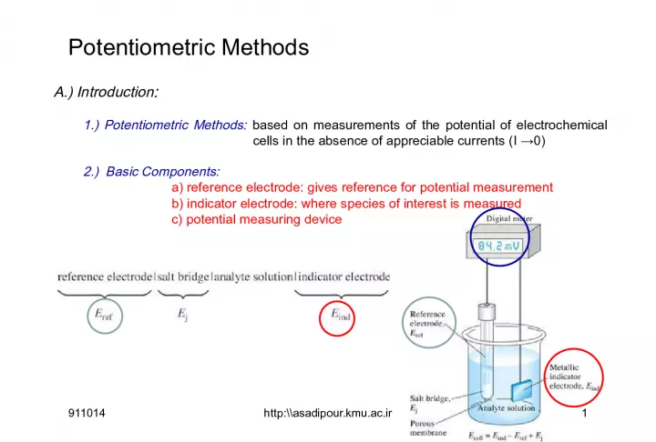
Slide1Potentiometric MethodsA.) Introduction : 1.) Potentiometric Methods: based on measurements of the potential of electrochemical cells in the absence of appreciable currents (I →0) 2.) Basic Components: a) reference electrode: gives reference for potential measurement b) indicator electrode: where species of interest is measured c) potential measuring device 911014 1 http:\\asadipour.kmu.ac.ir
Slide2Electrodes and Potentiometry Potential change only dependent on one ½ cell concentrations Reference electrode is fixed or saturated doesn’t change! Reference electrode, [Cl - ] is constant Potential of the cell only depends on [Fe 2+ ] & [Fe 3+ ] Pt wire is indicator electrode whose potential responds to [Fe 2+ ]/[Fe 3+ ] Unknown solution of [Fe 2+ ] & [Fe 3+ ] 911014 2 http:\\asadipour.kmu.ac.ir E cell =E cathod -E anod Anod is conventionally reference electode Fe 3+ +e - Fe 2+ AgCl (s) + e - → Ag + Cl -
Slide3B.) Reference Electrodes: (Instead of SHE) Need one electrode of system to act as a reference against which potential measurements can be made relative comparison. Standard hydrogen electrodes are cumbersome - Requires H 2 gas and freshly prepared Pt surface Desired Characteristics: a) known or fixed potential b) constant response c) insensitive to composition of solution under study d) obeys Nernest Equation e) reversible 911014 3 http:\\asadipour.kmu.ac.ir
Slide4Electrodes and PotentiometryReference Electrodes 1 .) Silver-Silver Chloride Reference Electrode E o = +0.222 V Activity of Cl - not 1 E (sat,KCl) = +0.197 V 911014 4 http:\\asadipour.kmu.ac.ir
Slide5Electrodes and PotentiometryReference Electrodes 2.) Saturated Calomel Reference Electrode (S.C.E) Saturated KCl maintains constant [Cl - ] even with some evaporation E o = +0.268 V Activity of Cl - not 1 E (sat,KCl) = +0.241 V 911014 5 http:\\asadipour.kmu.ac.ir
Slide6Electrodes and PotentiometryIndicator Electrodes 1.) three Broad Classes of Indicator Electrodes 1) Metal Electrodes - Develop an electric potential in response to a redox reaction at the metal surface 2) Ion-selective (Membrane) Electrodes - Selectively bind one type of ion to a membrane to generate an electric potential 3) Molecular Selective Electrode Remember an electric potential is generated by a separation of charge 911014 6 http:\\asadipour.kmu.ac.ir
Slide71) Metallic Indicator Electrode ( 3 Main Types) a) Metallic Electrodes of the First Kind b) Metallic Electrodes of the Second Kind c) Metallic Redox Indicators a) Metallic Electrodes of the First Kind i. Involves single reaction ii. Detection of catione derived from the metal used in the electrode iii. Example: use of copper electrode to detect Cu 2+ in solution ½ reaction: Cu 2+ + 2e - Cu (s) E ind gives direct measure of Cu 2+ : E ind = E o Cu – (0.0592/2) log a Cu(s) /a Cu 2+ since a Cu(s) = 1: E ind = E o Cu – (0.0592/2) log 1/a Cu 2+ or using pCu = -log a Cu 2+ : E ind = E o Cu – (0.0592/2) pCu 911014 7 http:\\asadipour.kmu.ac.ir
Slide8b) Metallic Electrodes of the Second Kind i. Detection of anion derived from the interaction with metal ion (M n+ ) from the electrode ii. Anion forms precipitate or stable complex with metal ion (M n+ ) iii. Example: Detection of Cl - with Ag electrode ½ reaction: AgCl(s) + e - Ag(s) + Cl - E O = 0.222 V E ind gives direct measure of Cl - : E ind = E o – (0.0592/1) log a Ag(s) a Cl - /a AgCl(s) since a Ag(s) and a AgCl(s) = 1 & E o = 0.222 V: E ind = 0.222 – (0.0592/1) log a Cl - 911014 8 http:\\asadipour.kmu.ac.ir
Slide9c) Metallic Redox Indicators i. Electrodes made from inert metals (Pt, Au, Pd) ii. Used to detect oxidation/reduction in solution iii. Electrode acts as e - source/sink iv. Example: Detection of Ce 3+ with Pt electrode ½ reaction: Ce 4+ + e - Ce 3+ E ind responds to Ce 4+ : E ind = E o – (0.0592/1) log a Ce 3+ /a Ce 4+ 911014 9 http:\\asadipour.kmu.ac.ir
Slide102) Membrane Indicator Electrodes a) General i. electrodes based on determination of cations or anions by the selective adsorption of these ions to a membrane surface. ii. Often called I on S elective E lectrodes (ISE) or pIon Electrodes iii. Desired properties of ISE’s 1) minimal solubility – membrane will not dissolve in solution during measurement. – silica, polymers, low solubility inorganic compounds , (AgX) can be used 2) Need some electrical conductivity 3) Selectively binds ion of interest 911014 10 http:\\asadipour.kmu.ac.ir
Slide11C+ diffuses across the membrane due to concentration gradient resulting in charge difference across membrane Electrodes and Potentiometry Indicator Electrodes Ion-Selective Electrodes Responds Selectively to one ion - Contains a thin membrane capable of only binding the desired ion Does not involve a redox process Membrane contains a ligand (L) that specifically and tightly binds analyte of interest (C + ) A difference in the concentration of C + exists across the outer membrane. The counter-ions (R - ,A - ) can’t cross the membrane and/or have low solubility in membrane or analyte solution Remember an electric potential is generated by a separation of charge Potential across outer membrane depends on [C+] in analyte solution 911014 11 http:\\asadipour.kmu.ac.ir
Slide12Electrodes and PotentiometryIndicator Electrodes Ion-Selective Electrodes Responds Selectively to one ion - Contains a thin membrane capable of only binding the desired ion Does not involve a redox process Remember an electric potential is generated by a separation of charge Potential across inner membrane depends on [C+] in filling solution, which is a known constant C + diffuses across the membrane due to concentration gradient resulting in charge difference across membrane A difference in the concentration of C + exists across the inner membrane. Electrode potential is determined by the potential difference between the inner and outer membranes: where E inner is a constant and E outer depends on the concentration of C + in analyte solution 911014 12 http:\\asadipour.kmu.ac.ir
Slide13Electrodes and PotentiometryIndicator Electrodes Ion-Selective Electrodes Responds Selectively to one ion - Contains a thin membrane capable of only binding the desired ion Does not involve a redox process Electrode Potential is defined as: where [C + ] is actually the activity of the analyte and n is the charge of the analyte 911014 13 http:\\asadipour.kmu.ac.ir
Slide14 pH Electrode i. most common example of an ISE based on use of glass membrane that preferentially binds H + ii. Typical pH electrode system is shown pH sensing element is glass tip of Ag/AgCl electrode Two reference electrodes here one SCE outside of membrane one Ag/AgCl inside membrane Combined electrod 911014 14 http:\\asadipour.kmu.ac.ir
Slide15Electrodes and PotentiometrypH Electrodes 1.) pH Measurement with a Glass Electrode Ag (s)| AgCl( s )|Cl - ( aq )||H + ( aq ,outside) H + ( aq ,inside),Cl - ( aq )|AgCl( s )|Ag( s ) Outer reference electrode [H + ] outside (analyte solution) [H + ] inside Inner reference electrode Glass membrane Selectively binds H + Electric potential is generated by [H + ] difference across glass membrane 911014 15 http:\\asadipour.kmu.ac.ir
Slide16iii. pH is determined by formation of boundary potential across glass membrane Boundary potential difference (E b ) = E 1 - E 2 where from Nernst Equation: E b = c – 0.592pH -log a H + (on exterior of probe or in analyte solution) constant Selective binding of cation (H + ) to glass membrane 911014 16 http:\\asadipour.kmu.ac.ir
Slide17Electrodes and PotentiometrypH Electrodes Glass Membrane Irregular structure of silicate lattice Cations (Na + ) bind oxygen in SiO 4 structure 911014 17 http:\\asadipour.kmu.ac.ir
Slide18Electrodes and PotentiometrypH Electrodes Glass Membrane Two surfaces of glass “swell” as they absorb water - Surfaces are in contact with [H + ] 911014 18 http:\\asadipour.kmu.ac.ir
Slide19Electrodes and PotentiometrypH Electrodes Glass Membrane H + diffuse into glass membrane and replace Na + in hydrated gel region - Ion-exchange equilibrium - Selective for H + because H + is only ion that binds significantly to the hydrated gel layer Charge is slowly carried by migration of Na+ across glass membrane Potential is determined by external [H + ] Constant and b are measured when electrode is calibrated with solution of known pH 911014 19 http:\\asadipour.kmu.ac.ir
Slide20iii. pH is determined by formation of boundary potential across glass membrane At each membrane-solvent interface, a small local potential develops due to the preferential adsorption of H + onto the glass surface. Glass Surface 911014 20 http:\\asadipour.kmu.ac.ir
Slide21Electrodes and PotentiometryJunction Potential 1.) Occurs Whenever Dissimilar Electrolyte Solutions are in Contact Develops at solution interface (salt bridge) Small potential (few millivolts) Junction potential puts a fundamental limitation on the accuracy of direct potentiometric measurements - Don’t know contribution to the measured voltage Again, an electric potential is generated by a separation of charge Different ion mobility results in separation in charge 911014 21 http:\\asadipour.kmu.ac.ir
Slide22iv. Alkali Error ‚ H + not only cation that can bind to glass surface - H + generally has the strongest binding ‚ Get weak binding of Na + , K + , etc ‚ Most significant when [H + ] or a H + is low (high pH) - usually pH $ 11-12 At low a H + (high pH), amount of Na + or K + binding is significant increases the “apparent” amount of bound H + 911014 22 http:\\asadipour.kmu.ac.ir
Slide23v. Acid Error ‚ Errors at low pH (Acid error) can give readings that are too high ‚ Exact cause not known - usually occurs at pH # 0.5 c) Glass Electrodes for Other Cations i. change composition of glass membrane ‚ putting Al 2 O 3 or B 2 O 3 in glass ‚ enhances binding for ions other than H + ii. Used to make ISE’s for Na + , Li + , NH 4 + 911014 23 http:\\asadipour.kmu.ac.ir
Slide24Example 18: The following cell was used for the determination of pCrO 4 : SCE||CrO 4 2- (xM), Ag 2 CrO 4 (sat’d)|Ag Calculate pCrO 4 if the cell potential is -0.386. 911014 24 http:\\asadipour.kmu.ac.ir
Slide2516-1 The shape of a redox titrationcurve • A redox titration is based on an oxidation-reduction reaction between analyte and titrant. • Consider the titration of iron(II) with standard cerium(IV), monitored potentiometrically with Pt and calomel electrodes . The potentials show above is in 1 M HClO 4 solution. Note that equilibria 16-2 and 16-3 are both established at the Pt electrode . 911014 25 http:\\asadipour.kmu.ac.ir
Slide26•There are three distinct regions in the titration of iron(II) with standard cerium(IV), monitored potentiometrically with Pt and calomel electrodes . 1. Before the equivalence point, where the potential at Pt is dominated by the analyte redox pair. 2. At the equivalence point, where the potential at the indicator electrode is the average of their conditional potential. 3. After the equivalence point, where the potential was determined by the titratant redox pair. 911014 26 http:\\asadipour.kmu.ac.ir
Slide27before the equivalence point: using analyte’s concentration to calculate E+ At the equivalence point: needs both redox pairs to calculate (why?) E of the cell 911014 27 http:\\asadipour.kmu.ac.ir
Slide28After the equivalence point:Summary • The greater the difference in reduction potential between analyze and titrant, the sharper will be the end point. • The voltage at any point in this titration depends only on the ratio of reactants; it will be independent of dilution . • Prior to the equivalence point, the half-reaction involving analyze is used to find the voltage because the concentrations of both the oxidized and the reduced forms of analyte are known. • After the equivalence point, the half-reaction involving titrant is employed. At the equivalence point, both half-reactions are used simultaneously to find the voltage. There are two special points during the above titration process: (1) when V = ½ V e, [Fe 3+ ] = [Fe 2+ ] and E + = E °(Fe 3+ | Fe 2+ ) ; (2) when V = 2 V e, [Ce 4+ ] = [Ce 3+ ] and E + = E °(Ce 4+ | Ce 3+ ) = 1.70 V. 911014 28 http:\\asadipour.kmu.ac.ir
Slide29•Titration curve.xlsx 911014 http:\\asadipour.kmu.ac.ir 29