Technical Support Team Members and Responsibilities

This article discusses the members of the technical support team, including Naomi Fitzsimmons who handles parts replacement, Matt Lapolla who works on programming and technical issues, John Robertson who deals with policies,
- Uploaded on | 4 Views
-
 afinapristayko
About Technical Support Team Members and Responsibilities
PowerPoint presentation about 'Technical Support Team Members and Responsibilities'. This presentation describes the topic on This article discusses the members of the technical support team, including Naomi Fitzsimmons who handles parts replacement, Matt Lapolla who works on programming and technical issues, John Robertson who deals with policies,. The key topics included in this slideshow are . Download this presentation absolutely free.
Presentation Transcript
Slide1
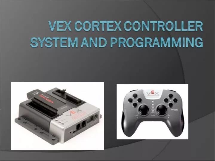
Slide2Who are we? Naomi Fitzsimmons naomi.fitzsimmons@student.oc.edu Parts replacement Matt Lapolla okbest@mattandsuz.com Programming, Technical issues, Rules, etc. John Robertson johndrobertson@gmail.com Policies, Technical Issues, Scoring Bill Ryan Bill.Ryan@oc.edu Everything else
Slide3Overview Terminology Hardware Overview Programming Languages Installing Easy C Programming example Defining Inputs Defining Outputs Input - Output Relationship Write Program Test Program Other Useful Functions Appendix
Slide4
Slide5Terminology:Proportional or Non-Proportional Press to Play Proportional (Analog) Non-Proportional (Digital) Regular Light Switch Dimmer Light Switch
Slide6Servo vs Motor0 32 64 127 -32 -64 -127 Transmitter Cortex Controller Servo Motor QUESTIONS ? QUESTIONS ? Robot
Slide7Terminology:Programming software Compile – changes your C program into object code that the linker understands. Link – combines your program’s object code with the Intelitek library and other libraries to create code that is executable on the Cortex processor. Download / Bootload – transfers the machine code version of your program from the PC to the Cortex where it will execute (the IFI/Intelitek Loader will perform the transfer via the PC USB cable)
Slide8
Slide9Hardware Overview:Joystick 2 XY analog joysticks 8 buttons on top Plug-in USB/ WiFi Key 4 Button on front-side Partner/ Buddy Control Support 3 Axis Accelerometer (XY Tilt, XYZ Accel, Shake) Power switch 6 AAA rechargeable batteries
Slide10Hardware Overview:Joystick – What you will use 2 XY analog joysticks 8 buttons on top Plug-in USB/ WiFi Key 4 Button on front-side Partner/ Buddy Control Support 3 Axis Accelerometer (XY Tilt, XYZ Accel, Shake) Power switch 6 AAA rechargeable batteries 3 Axis Accelerometer (XY Tilt)
Slide11Hardware Overview:Cortex Controller USB Analog in Digital in/out 2-wire motor Standard Serial Interfaces (UART, I2C) Speaker Out 1 12 1 8 SP 1 9 2-wire motor 3-wire PWM servo/motor ctrl 2 10
Slide12Hardware Overview:Cortex Controller – What you will use USB Analog in Digital in/out 2-wire motor Standard Serial Interfaces (UART, I2C) Speaker Out 1 12 1 8 SP 1 9 2-wire motor 3-wire PWM servo/motor ctrl 2 10 Digital in
Slide13Hardware Overview:Cortex Controller backup battery port for WiFi communications (9V) 75MHz crystal interface ports On/Off switch main battery port (7.2V) configuration switch (used for special procedures) This will only be important on Game Day. Install before each match. Remove after each match.
Slide14Hardware Overview:Cortex Controller – What you will use backup battery port for WiFi communications (9V) 75MHz crystal interface ports On/Off switch main battery port (7.2V) configuration switch (used for special procedures)
Slide15Hardware Overview:Cortex Controller Ground + 5V Signal/Control + Battery Power + Motor Power (for + control input) - Motor Power (for – control input)
Slide16Hardware Overview:DC Motors Do not solder to motors. Use spade connectors instead. Polarity is NOT marked on motors: positive(+), negative(-) Wiring and programming will determine clockwise or counter clockwise rotation for positive stick movement Mount motors with 8-32 machine screws Machine screws must be cut to proper length to avoid motor damage! max screw depth= ~1/8” (small motor) ~1/4” (large motor)
Slide17 If using built-in motor controller(s) connect via 2-wire screw terminal cables (red/black) use motor ports 1 & 10 only If using external motor controller(s) connect via 3-wire external motor controller + 2-wire screw terminal cable use motor ports 2 thru 9 only Hardware Overview: DC Motors
Slide18Hardware Overview:2 wire Motor connection Ports 1, 10 Port 1 and Port 10 Built-In Motor Controllers Connector is not keyed. Allows swapping polarity. Screw terminals for attaching motor wires
Slide19Hardware Overview:3 wire Motor connection Ports 2 - 9 External Motor Controller Standard 2-wire motor cable Standard 3-wire PWM connector Plug in to Motor Ports 2 thru 9 Suggest using a 4” wire tie or heat shrink tubing here Screw terminals for attaching motor leads
Slide20Hardware Overview:Servo – Electrical Connection Futaba S3003 or S3004 series Maximum 120 degree rotation (+60, -60) Connection to Cortex controller via 3-wire PWM + 2x3 pin header use motor ports 2 thru 9 only Servo horns may be modified 2x3 pin header servo horns (2) (2) (1)
Slide21Hardware Overview:Servo – Electrical Connection Insert a 2x3 pin header Occupies 2 ports Converts VEX female port to male port Because Futaba servos have female connectors
Slide22Hardware Overview:Servo – Electrical Connection Servo connectors are keyed for proper insertion. (small tab shown) Servo Cables White= Data Red = +Batt Voltage Black = Gnd Second half of 2x3 pin header.
Slide23Hardware Overview:Servo – Mounting Hardware Futaba 3003/3004 Servos 4 per Kit Mounting Hardware for each To eliminate damage to mounting holes Servo Mounting Hardware Rubber grommet (2) Brass spacer (4) Mounting screw (4) Note: There are 16 of each screw, spacer, grommet in the Return Kit.
Slide24Hardware Overview:Servo – Mounting Hardware 1. No h/w attached 2. Attach rubber grommets 3. Insert brass spacers 4. Secure servo with screws
Slide25Hardware Overview:Digital Input/Output Use for switches Connect to Cortex digital inputs using 2-wire sensor screw terminal cables (white/black wires) sensor screw terminal cable Connect to switch Connect to Cortex digital input port
Slide26Hardware Overview:Digital Input / Output must program digital port for proper direction (input) Open: Program reads as ‘1’ ; Closed: Program Reads as ‘0’ use digital ports 1 thru 12 sensor cable connector is keyed
Slide27
Slide28Programming Languages Best Inc provides 3 different programming languages: Simulink by The Mathworks Robot C by Carnegie Mellon University Robotics Academy Easy C by Intelitek
Slide29Programming Languages:Simulink Is a graphical simulation/programming environment Links with Easy C for compiling and programming OK BEST support will be limited by our lack of knowledge. We haven’t even been given a copy of the software to test.
Slide30Programming Languages:Robot C Created by Carnegie Mellon University Leader in the robot world Has debugging feature OKBEST has a copy of the software Support will be limited – our introduction webinar is scheduled for September 8 th and lasts 6 weeks. Website available http://www.education.rec.ri.cmu.edu/fire/competitions/ best/ Look for items containing Cortex Controller
Slide31Programming Languages:Easy C A graphical programming language Still need a basic understanding of programming in C Good for rapid simple programming Applicable for most teams needs Highly supportable by OKBEST staff
Slide32
Slide33Installing Easy C:What you will need Minimum System Requirements Windows XP/Vista/Win7, Mac not supported PIII-450MHz+, 256MB+ RAM, 120MB Hard Disk Space Administrator Access on the PC 1 USB port available for Cortex programming Software & Installation Software provided on CD Installer auto runs from CD 4-month license begins at installation, 3 seats Updates available at http://www.intellitekdownloads.com
Slide34Installing Easy C:What is installed Prolific USB to Serial Driver EasyC Integrated Development Environment IFI/Intelitek Loader EasyC libraries IFI VEXnet firmware upgrade* Many example projects 14 Integrated Tutorials * Note: Firmware upgrade requires administrator mode on Windows VISTA. Right click on “IFI VEXnet Firmware Upgrade” in Programs Menu and select “Run as administrator”.
Slide35Installing Easy C:What you will need Projects and Libraries are added here My Documents\Intelitek\easyC V4 for Cortex
Slide36Installing Easy C:Installing Application Must be in the administrator account (or administrator mode) Run the easyC_V4_for_Cortex4001.exe program Follow the on screen instructions Check the “Install Prolific USB to Serial adapter driver“ checkbox before clicking the Finish button, the driver installer will startup after a few seconds Sample files copied into a “Intelitek” subfolder in the Documents (or My Documents in XP) folder Sample files must be copied to each users folder if the software will be shared by multiple users on the same machine.
Slide37Installing Easy C:Installing Application On the first startup of the software, there will a prompt for registration code Enter the registration code provided with your CD
Slide38
Slide39Programming Example:Steps to creating a program Open new Easy C workspace Define Inputs Define Outputs Define Input to Output relationship Write a program Compile Program Download Test Program
Slide40Programming Example:Open Easy C
Slide41Programming Example:Open New Project
Slide42Programming Example:Open New Project
Slide43Programming Example:Save your New Program
Slide44Programming Example
Slide45Defining Inputs:Joystick, Switches and Digital Signals Joystick Input Options Proportional Channel 1 Channel 2 Channel 3 Channel 4 Tilt X Tilt Y Digital Inputs Channel 5 Up, Down Channel 6 Up, Down Channel 7 U, D, R, L Channel 8 U, D, R, L Controller Input Options Digital 1 Digital 2 Digital 3 Digital 4 Digital 5 Digital 6 Digital 7 Digital 8 Digital 9 Digital 10 Digital 11 Digital 12 What are the Inputs?
Slide46Defining Inputs:Joystick, Switches and Digital Signals Channel 1 Drive: Turn Right Left Channel 2 Drive: Forward/Reverse Joystick Input Options Proportional Channel 1 Channel 1 Channel 2 Channel 2 Channel 3 Channel 4 Tilt X Tilt Y Digital Inputs Channel 5 Up, Down Channel 6 Up, Down Channel 7 U, D, R, L Channel 8 U, D, R, L Controller Input Options Digital 1 Digital 2 Digital 3 Digital 4 Digital 5 Digital 6 Digital 7 Digital 8 Digital 9 Digital 10 Digital 11 Digital 12
Slide47Defining Inputs:Joystick, Switches and Digital Signals Channel 1 Drive: Turn Right Left Channel 2 Drive: Forward/Reverse Channel 3 Arm: Raise and Lower Joystick Input Options Proportional Channel 1 Channel 2 Channel 3 Channel 3 Channel 4 Tilt X Tilt Y Digital Inputs Channel 5 Up, Down Channel 6 Up, Down Channel 7 U, D, R, L Channel 8 U, D, R, L Controller Input Options Digital 1 Digital 2 Digital 3 Digital 4 Digital 5 Digital 6 Digital 7 Digital 8 Digital 9 Digital 10 Digital 11 Digital 12
Slide48Defining Inputs:Joystick, Switches and Digital Signals Channel 1 Drive: Turn Right Left Channel 2 Drive: Forward/Reverse Channel 3 Arm: Raise and Lower Digital 1 Arm: Upper Limit Digital 2 Arm: Lower Limit Joystick Input Options Proportional Channel 1 Channel 2 Channel 3 Channel 4 Tilt X Tilt Y Digital Inputs Channel 5 Up, Down Channel 6 Up, Down Channel 7 U, D, R, L Channel 8 U, D, R, L Controller Input Options Digital 1 Digital 1 Digital 2 Digital 2 Digital 3 Digital 4 Digital 5 Digital 6 Digital 7 Digital 8 Digital 9 Digital 10 Digital 11 Digital 12
Slide49Defining Inputs:Joystick, Switches and Digital Signals Channel 1 Drive: Turn Right Left Channel 2 Drive: Forward/Reverse Channel 3 Arm: Raise and Lower Digital 1 Arm: Upper Limit Digital 2 Arm: Lower Limit Channel 5 Up Wrist: Rotate Up Channel 5 Down Wrist: Rotate Down Joystick Input Options Proportional Channel 1 Channel 2 Channel 3 Channel 4 Tilt X Tilt Y Digital Inputs Channel 5 Up, Down Channel 5 Up, Down Channel 6 Up, Down Channel 7 U, D, R, L Channel 8 U, D, R, L Controller Input Options Digital 1 Digital 2 Digital 3 Digital 4 Digital 5 Digital 6 Digital 7 Digital 8 Digital 9 Digital 10 Digital 11 Digital 12
Slide50Programming Example
Slide51Defining Outputs:Motors and Servos Motor / Servo Output Options Proportional Channel 1* Channel 2# Channel 3# Channel 4# Channel 5# Channel 6# Channel 7# Channel 8# Channel 9# Channel 10* * Can drive motor Direct, No servo control # Can drive servo Direct, Motor with speed controller
Slide52Defining Outputs:Motors and Servos Motor / Servo Output Options Proportional Channel 1* Channel 2# Channel 3# Channel 4# Channel 5# Channel 6# Channel 7# Channel 8# Channel 9# Channel 10* * Can drive motor Direct, No servo control # Can drive servo Direct, Motor with speed controller
Slide53Defining Outputs:Motors and Servos Motor / Servo Output Options Proportional Channel 1* Channel 2# Channel 3# Channel 4# Channel 5# Channel 6# Channel 7# Channel 8# Channel 9# Channel 10* * Can drive motor Direct, No servo control # Can drive servo Direct, Motor with speed controller What are the outputs?
Slide54Defining Outputs:Motors and Servos Channel 1 (Motor Large) Right Drive Motor Channel 10 (Motor Large) Left Drive motor Motor / Servo Output Options Proportional Channel 1* Channel 1* Channel 2# Channel 3# Channel 4# Channel 5# Channel 6# Channel 7# Channel 8# Channel 9# Channel 10* Channel 10* * Can drive motor Direct, No servo control # Can drive servo Direct, Motor with speed controller
Slide55Defining Outputs:Motors and Servos Channel 1 (Motor Large) Right Drive Motor Channel 10 (Motor Large) Left Drive motor Channel 2 (Motor Small) Raise and Lower Arm Motor / Servo Output Options Proportional Channel 1* Channel 2# Channel 2# Channel 3# Channel 4# Channel 5# Channel 6# Channel 7# Channel 8# Channel 9# Channel 10* * Can drive motor Direct, No servo control # Can drive servo Direct, Motor with speed controller
Slide56Defining Outputs:Motors and Servos Channel 1 (Motor Large) Right Drive Motor Channel 10 (Motor Large) Left Drive motor Channel 2 (Motor Small) Raise and Lower Arm Channel 3 (Servo) Wrist: Rotate Up/Down Motor / Servo Output Options Proportional Channel 1* Channel 2# Channel 3# Channel 3# Channel 4# Channel 5# Channel 6# Channel 7# Channel 8# Channel 9# Channel 10* * Can drive motor Direct, No servo control # Can drive servo Direct, Motor with speed controller
Slide57Programming Example
Slide58Input – Output Relationship:Flow Chart, Pseudo-code Channel 1 Channel 2 Arcade Mixing Motor 1 (Right) Motor 10 (Left) Inputs Outputs Program Channel 3 Channel 3 If not at limit Digital 1 Digital 2 Motor 2 (Arm) Channel 5 Up Channel 5 Down Up = Rotate Up Down = Rotate Down Servo 3 (Wrist)
Slide59Programming Example
Slide60Write Program:Set Up Input / Output The Controller Configuration window is used to identify what the various interfaces will be used for and whether the digital interfaces are configured as inputs or outputs. The Controller Configuration window can be accessed via the Project menu. The example shown is the BEST default program.
Slide61Write Program:COMMENT..COMMENT!!!! Drag
Slide62Write Program:COMMENT..COMMENT!!!!
Slide63Write Program:COMMENT..COMMENT!!!!
Slide64Write Program:Endless Loop Drag 1 = Always
Slide65Write Program:Endless Loop Most of your program will be inside the endless loop
Slide66Write Program:Drive Motors Channel 1 Channel 2 Arcade Mixing Motor 1 (Right) Motor 10 (Left) Inputs Outputs Program
Slide67Write Program:Drive Motors Drag
Slide68Write Program:Drive Motors
Slide69Write Program:Drive Motors Drag
Slide70Write Program:Drive Motors Always Joystick #1 Set Right Motor to Motor/Servo Port 1 Set Left Motor to Motor/Servo Port 10
Slide71Write Program:Drive Motors
Slide72Write Program:Arm Raise/Lower Channel 1 Channel 2 Arcade Mixing Motor 1 (Right) Motor 10 (Left) Inputs Outputs Program Channel 3 Channel 3 If not at limit Digital 1 Digital 2 Motor 2 (Arm)
Slide73Write Program:Arm Raise/Lower Drag
Slide74Write Program:Arm Raise/Lower Drag
Slide75Write Program:Arm Raise/Lower Always Joystick #1 Channel 3 Motor/Servo 2 Limit Switch Input 1 Limit Switch Input 2
Slide76Write Program:Arm Raise/Lower
Slide77Write Program:Wrist Rotate Channel 1 Channel 2 Arcade Mixing Motor 1 (Right) Motor 10 (Left) Inputs Outputs Program Channel 3 Channel 3 If not at limit Digital 1 Digital 2 Motor 2 (Arm) Channel 5 Up Channel 5 Down Up = Rotate Up Down = Rotate Down Servo 3 (Wrist)
Slide78Write Program:Wrist Rotate
Slide79Write Program:Wrist Rotate Servo Port 3 Joystick Channel 5 Select Down Button Select Up Button Set Servo Value Set Servo Value
Slide80Programming Example
Slide81Compile and Download:Build and Download
Slide82Compile and Download:Verify Compile with No Errors
Slide83Compile and Download:Download Program to Cortex When you see the following message connect your Cortex Controller to the PC using the supplied USB A-A cable. Then click on the YES button.
Slide84Compile and Download:Download Program to Cortex Hopefully you will see this. Then click on the OK button.
Slide85Programming Example
Slide86Test Program Ensure your robot is ‘safe’ to operate: Can’t move or fall off table (use a jack-stand) All team members clear of moving parts Connect either WiFi keys or tether cable between the joystick and the Cortex controller. Make sure Cortex switch is in OFF position. Attach a charged battery. Turn on joystick (if not using tether). Turn Cortex switch to ON position. For WiFi comm, link should establish in ~10 sec Test robot operations with transmitter.
Slide87Programming Example
Slide88Other Useful Functions Program Flow If Conditional Else-IF Conditional Else Conditional While Loop While condition is True … For Loop Repeat for X number of times Comment PLEASE COMMENT!
Slide89Other Useful Functions Inputs Digital Input…Gets Status of Digital Input Outputs Motor Module…Directly send value to motor Servo Module…Directly send value to servo
Slide90Other Useful Functions Joystick Arcade – 2 Motor ○ Use Arcade style joystick inputs and drive 2 motors Tank-2 Motor ○ Use Tank style joystick inputs and 2 drive motors Joystick to Motor ○ Take input from 1 joystick and send it to motor
Slide91Other Useful Functions Joystick Joystick to Motor & Limit ○ Take joystick value straight to motor if not at limit Joystick to Servo ○ Take a joystick value and send it to a servo Joystick Digital to Motor ○ Select 2 speeds for a motor based on joystick buttons pressed Joystick Digital to Motor & Limit ○ Select 2 speeds for a motor based on joystick buttons pressed, unless limit is reached
Slide92Other Useful Functions Joystick Joystick Digital to Servo ○ Select one of 2 positions of a servo based on 2 buttons on the joystick Get Joystick to Analog ○ Retrieves a joystick value to a variable Get Joystick to Digital ○ Retrieves a joystick button to a variable
Slide93
Slide94Appendix: Resources http://best.eng.auburn.edu/b_resources. php Not all information is relevant to BEST competition Robot C for Cortex controller http://www.education.rec.ri.cmu.edu/product s/teaching_robotc_cortex/index.html
Slide95Appendix: Re-sync Controller1. Turn off Cortex and Joystick 2. Connect A-A USB cable to Cortex and Joystick 3. Turn on Joystick OR Cortex 4. Wait for Green Vexnet Light on both Joystick and Cortex 5. Turn off both Joystick and Cortex 6. Disconnect cables
Slide96Appendix - Status Lightsjoystick battery status robot battery status comm. link status Game status (not used by BEST) • Green battery – good charge • Yellow battery - dying • Red battery – dead • Green VEXnet – comm. established • Yellow VEXnet – searching • Lights on the controller and the joystick are the same
Slide97Appendix – Team Tips Tin motor wires with solder before attaching to screw terminals since frayed stranded wires can cause a short. Do NOT solder wires to Cortex connectors! Sensor cables, servo wires, and servo extensions are all keyed in correct orientation; insert and remove carefully to avoid destroying connectors. Tighten screws on motor and sensor connector cables so that wires are not loose and do not pull out. Mount Cortex to robot using #8 screws through holes provided; be careful not to over tighten. Avoid “hot insertion” of USB Keys. You may operate tethered by removing the USB WiFi key and connecting a USB A-A cable between joystick and Cortex.
Slide98Appendix - Joystick Calibration If the motors hum or creep (sticks not returning to zero), the joystick may need to be recalibrated Calibration procedure (as extracted from the easyC help file) 1) The Joystick must be "Linked" to the Cortex Microcontroller using the VEXnet Keys. 2) Hold the "6U" Back Switch depressed. 3) While the "6U" Back Switch is depressed, use a small Allen Wrench (1/16" or smaller) or similar small straight tool to depress and hold the CONFIG Switch. 4) Hold both Switches depressed until you see the Joystick LED Flash RED and GREEN - you can now release both Switches. a. There is a 10 second time limit to complete the following steps 5 and 6. 5) Now move both Joystick Pots to the maximum position desired in all 4 directions - Up, Back, Left, and Right. a. If a movement is not detected in all 4 directions, a timeout will occur after about 10 seconds and the Cal Mode will be discontinued and the VEXnet LED will briefly Flash Red. b. The Joystick LED will continue to Flash RED and GREEN during the calibration process. 6) After movement is detected in all 4 directions, the Joystick LED will be ON and Solid GREEN. a. To "Save" the Calibration, depress and release the "8U" Top Switch Button. b. If the calibration is accepted and Saved, the Joystick LED will start Flashing Fast GREEN for a few seconds. c. If the Calibration is not Saved, a timeout will occur after about 10 seconds and the Cal Mode will be discontinued and the VEXnet LED will briefly Flash Red. d. To cancel a calibration, depress and release the "7U" Top Switch Button. The Cal Mode will be discontinued and the VEXnet LED will briefly Flash Red. e. If the Cal Mode is discontinued or saved, the Joystick LEDs will resume their normal function after the VEXnet LED briefly Flashes.
Slide99Appendix – Default ProgramMotor/Servo Output Joystick Channel Motor Limits Positive Direction Negative Direction Motor 1 (Arcade Right) Channel 1 (Lt, Rt) Channel 2 (Fwd/Rev) None None Motor 2 Channel 1 Digital Input 1 Digital Input 2 Motor 3 Channel 2 Digital Input 3 Digital Input 4 Motor 4 Channel 3 Digital Input 5 Digital Input 6 Motor 5 Channel 4 Digital Input 7 Digital Input 8 Motor 6 Channel 3 None None Motor 7 Channel 3 Inverse None None Motor 8 Channel 4 None None Motor 9 Channel 4 Inverse None None Motor 10 (Arcade Left) Channel 1 (Lt, Rt) Channel 2 (Fwd/Rev) None None